


AXIS P3365-V Fixed Dome Network Camera
Technical Specifications
Function/group
Item
Specications
VCCI Class B
C-tick AS/NZS CISPR 22 Class B
IEC/EN/UL 60950-1
IEC 60068-2-1, IEC 60068-2-2, IEC 60068-2-14, IEC 60068-2-27, IEC 60068-2-64,
IEC 60068-2-78
IEC 62262 IK10
KCC KN 22 Class B, KN 24
Dimensions
(HxWxD)
104 x 148 x 148 mm (4.1 x 5.8 x 5.8 in)
Weight
730 g (1.6 lb.)
Included
accessories
Drill hole template, Installation Guide, Windows decoder 1-user license, 1 resitorx screw
driver, smoked dome cover, connector kit
Video
management
software (not
included)
AXIS Camera Companion, AXIS Camera Station, Video management software from Axis’
Application Development Partners available on www.axis.com/techsup/software
Optional
accessories
P51-rated Recessed Mount Kit with transparent or smoked cover
Mounting bracket
AXIS T94H01P Conduit Back Box
Pendant adapter kit
AXIS T91A Brackets
For more accessories, see www.axis.com
Languages
German, French, Spanish, Italian, Russian, Simplied Chinese, Japanese, Korean,
Portuguese
Warranty
Axis 3–year warranty and AXIS Extended Warranty option, see www.axis.com/warranty
Connectors
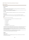
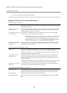
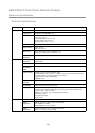
I/O Connector
4-pin terminal block
1 2 3 4
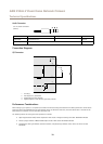
For an example diagram, see Connection Diagrams on page 70.
Function Pin Notes
Specications
0 V DC (-)
1
0 V DC
DC output
2
Can be used to power auxiliary equipment.
Note: This pin can only be used as power out.
3.3 V DC
Max load = 50 mA
Digital input
3
Connect to pin 1 to activate, or leave oating (unconnected)
to deactivate
0 to max 40 V DC
Digital output
4
Connected to pin 1 when activated, oating (unconnected)
when deactivated. If used with an inductive load, e.g. a relay,
a diode must be connected in parallel with the load, for
protection against voltage transients.
0 to max 40 V DC, open drain,
100 mA
69