


Wireless Mode
Description
The TR-24 has the ability to be booted in one of three modes.
These modes are wireless, wired and master wireless. This
section will discus the wireless mode.
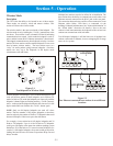
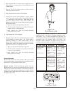
The wireless mode is the most used mode of the beltpack. The
wireless mode is set by holding the <TALK> button down as the
unit boots. Then release it once a channel LED has lit indicating
communication has started. In this mode the beltpack’s radio is
active and the bottom RJ-45 Ethernet connection is deactivated.
The beltpack communicates to other beltpacks wireless via a base
station (This base station could be another beltpack if it was set to
boot in master wireless mode.). The base station serves as a
“relay” for audio packets going between beltpacks. One base
station can serve up to ten beltpacks in full duplex mode
(simultaneous talk and listen).
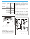
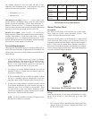
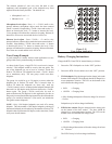
Figure 5-1
Ten Beltpacks in Wireless Mode
With ten beltpack in full duplex, up to 28 additional beltpacks can
work off the base station if these beltpacks are in Push-to-TX
mode. In Push-to-TX mode the beltpacks are listen only and the
beltpacks’ channel lights are flashing until the <TALK> button is
active. At that point the beltpack transmits full time and is in full
duplex mode until user disables the <TALK> button again.
NOTE: Only ten full duplex beltpacks can work off a base
station. Thus the number of full duplex beltpacks on that base
must be reduce by the number of Push-to-TX beltpacks that could
become full duplex if their users press the talk button.
For example, a base station has 6 full duplex beltpacks and 28
Push-to-TX beltpacks. Up to 4 of the 28 Push-to-TX beltpacks
could go to full duplex at the same time without reaching system
limitations. If 5 of the Push-to-TX were to become full duplex, for
a total of 11 full duplex beltpacks, the system would go beyond its
loading limit and all users will start to experience drop outs and
delays in audio.
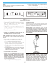
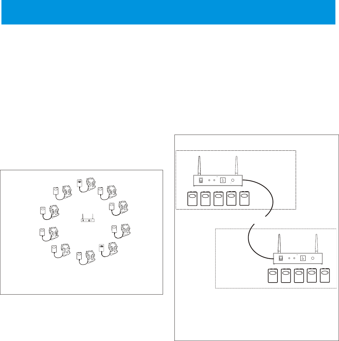
Multiple base stations can also be utilized in an installation. The
base stations have the ability to communicate to each other via an
Ethernet network connected to the RJ-45 jack on the rear panel.
The connection between bases could be a direct connection via an
Ethernet cable (100m, 328ft Max.) or connected via the
building’s Ethernet infrastructure (See “Network Information” in
the “Wired Mode” discussion for details.). Due to the base
station’s wired interconnection, the beltpacks of the various base
stations can communicate with each other.
Ten full duplex beltpacks is still the limit even if multiple base
stations, connected via Ethernet, in non-overlapping RF coverage
areas, are in a system.
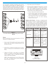
Figure 5-2
Two Ethernet connected base stations in two different
locations.
Section 5 - Operation
5-1
ON
OFF
LOW
BATTERY
POWER
AP
ACTIVE
CHANNEL
Telex
R
SELECT
CHANNEL
CLEAR SCAN
LOCK
BTR-24
Telex
TR-24
R
Telex
TR-24
R
Telex
TR-24
R
Telex
TR-24
R
Telex
TR-24
R
Telex
TR-24
R
Telex
TR-24
R
Telex
TR-24
R
Telex
TR-24
R
Telex
TR-24
R
ON
OFF
LOW
BATTERY
POWER
AP
ACTIVE
CHANNEL
Telex
R
SELECT
CHANNEL
CLEAR SCAN
LOCK
BTR-24
ON
OFF
LOW
BATTERY
POWER
AP
ACTIVE
CHANNEL
Telex
R
SELECT
CHANNEL
CLEAR SCAN
LOCK
BTR-24
CONNECTED BY ETHERNET CABLE
LOCATION
1
LOCATION
2
Telex
TR-24
R
Telex
TR-24
R
Telex
TR-24
R
Telex
TR-24
R
Telex
TR-24
R
Telex
TR-24
R
Telex
TR-24
R
Telex
TR-24
R
Telex
TR-24
R
Telex
TR-24
R