


The sidetone (amount of your own voice fed back to your
earphones) and microphone gain of the beltpacks may need
adjusted from the factory defaults. The defaults are:
• Microphone Level = 4
• Sidetone Level = 2
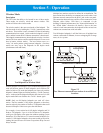
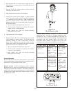
Microphone Level Adjust – Press <1> + <TALK> until a voice
prompt indicates microphone adjust mode has been entered
(about 3 seconds). Keep holding <TALK> down and use the <1>
button to decrease the level, <2> button to increase the level.
Voice prompts will indicate the current level setting. Release all
buttons for at least one second and the level will be set.
Sidetone Level Adjust – Press <TALK> + <2> until a voice
prompt indicates sidetone adjust mode has been entered (about 3
seconds). Keep holding <TALK> down and use the <1> button
to decrease the level, <2> button to increase the level. Voice
prompts will indicate the current level setting. Release all buttons
for at least one second and the level will be set.
Network Requirements
These network requirements apply to interconnect BTR-24s as
well as TR-24 in wired mode. In general the TR-24 and BTR-24s
following the same rules as other Ethernet networked devices.
These rules are:
1. All TR-24s and BTR-24 must have unique IP (Internet
Protocol) addresses. This means no TR-24s or BTR-24s in a
network should have the same IP address. Also, no other
devices on the wired network should have the same IP
addresses as the BTR-24s and TR-24s to be used.
2. Use category 5e or better Ethernet cables that are wired to
standards T-568A or T-568B (Most all Ethernet cables are
built to these standards.).
3. If direct connecting TR-24s or BTR-24s together, without
the use of a building’s network infrastructure, do not use
more than 100m (328ft) of Ethernet cable between devices.
4. If using an existing building’s Ethernet network, consult
your network administrator as to the locations you plan on
connecting your TR-24 or BTR-24s to the network. They
can then check to make sure distance limitations of the
network are met and that existing in-house router/switchers
are set to pass TR-24 and BTR-24 packets.
NOTE: All TR-24 and BTR-24 devices will appear to have
the same MAC address to a network.
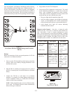
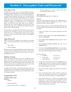
TR-24/BTR-24 Wired Data Packets
Master Wireless Mode
Description
The TR-24 has the ability to be booted in one of three modes.
These modes are wireless, wired and master wireless. This
section will discuss the master wireless mode.
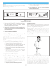
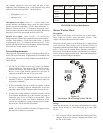
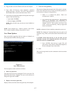
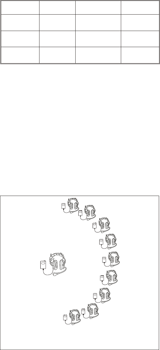
The master wireless mode is set by holding the <1> button down
as the unit boots. Then release it once a channel LED has lit
indicating communication has started. In this mode the beltpack’s
radio is active and the bottom RJ-45 Ethernet connection is
deactivated. This beltpack not only still functions as a beltpack,
its now acting as a base station as well. One master beltpack can
serve up to 9 other full duplex beltpacks.
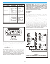
Figure 5-9
One master TR-24 serving 9 other TR-24's
Set-up
Below are instructions for the set-up and operation of a single
master TR-24 serving as a base station for up to nine other
TR-24s.
1. Prior to use the TR-24s should have their battery packs fully
charged. Refer to the “Battery Charging Instructions” near
the end of this section.
5-5
Description IP Type Destination IP Protocal
Audio 1
Packet
Multicast 239.192.168.1 UDP
Audio 2
Packet
Multicast 239.192.168.2 UDP
Audio 1 + 2
Packet
Multicast 239.192.168.3 UDP
Telex
TR-24
RR
MASTER TR-24
SERVING AS A
BASE STATION
Telex
TR-24
RR
Telex
TR-24
RR
Telex
TR-24
RR
Telex
TR-24
RR
Telex
TR-24
RR
Telex
TR-24
RR
Telex
TR-24
RR
Telex
TR-24
RR
Telex
TR-24
RR