


2.5.4 Power Connection
BKP-4: Plug an power cord (not supplied) into the power
connector and into any 90-240 VAC, 47-63 Hz main
power source.
TKP-4 / WKP-4: Connect an optional AC adapter using
the color-code information on the AC adapter and the ter
-
minal pinout information in Figure 7
. Alternatively, con
-
nect any well regulated and filtered 15 VDC, 1 amp
power source to the power terminals.
2.6 STARTUP AND OPERATIONAL CHECK
When power is applied, all LEDs will first flash red, then
green. This confirms that all LEDs are working correctly.
Also, the call waiting window will display asterisks (
****
)
then dashes (----).
☞
If the keypanel cannot establish data communications
with the intercom system, asterisks will continue to
display. Check the intercom cable connections (in
particular, the data connections).
Several symptoms may occur if the keypanel address is in
-
correctly set: 1) there may be no indication when there is an
incoming call; 2) when an intercom key is pressed to talk,
the destination may not hear the audio, 3) the call waiting
display may behave erratically. If any of these symptoms
occur, recheck the keypanel Address switch setting.
☞
Important! Always reset the keypanel after changing
the Address switch setting. Do this by briefly
removing power to the keypanel.
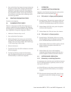
If installing a WKP-4, assemble the front panel into the
mounting box using the screws supplied with the WKP-4.
This completes the standard installation procedures.
User Instructions BKP-4, TKP-4, and WKP-4 Keypanels 13
DE-9P (MALE)
TO KEYPANEL
DE-9S (FEMALE)
TO INTERCOM SYSTEM*
CABLE TYPE:
BELDEN 8777
1
2
6
4
5
9
7
8
3
1
2
6
4
5
9
7
8
3
DATA
AUDIO TO MATRIX
AUDIO FROM MATRIX
+
-
+
-
-
+
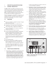
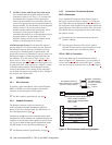
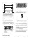
When connecting to an ADAM CS back panel, use
only low-profile cable connectors such as AMP
Part No. 747516-3 (Telex Part No. 59926-678)
IMPORTANT!
*
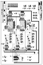
Figure 6. 9-pin Intercom cable wiring diagram.
Important: Shield connections at keypanel end are
optional and may cause ground loops if used.
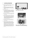
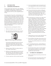
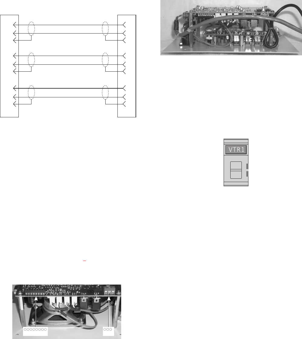
876543 21 3 2 1
INTERCOM POWER
PIN 1:DATA PLUS (+)
PIN 2:DATA MINUS (-)
PIN 3;NO CONNECTION
PIN 4:AUDIOTO MATRIX PLUS (+)
PIN 5:AUDIOTO MATRIX MINUS (-)
PIN 6;NO CONNECTION
PIN 7:AUDIO FROM MATRIX MINUS (-)
PIN 8:AUDIO FROM MATRIX PLUS (+)
PIN 1:PLUS (+) 15 VDC
PIN 2:NO CONNECTION
PIN 3:COMMON (GND)
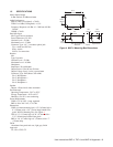
Figure 7. Intercom and Power Terminal Block
Pinouts for the TKP-4 / WKP-4.
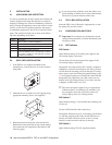
Figure 8. Use tie wraps to secure the cables
(WKP-4 installation).
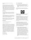
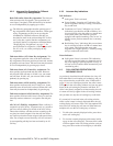
Call waiting
Figure 9. Call Waiting Window and Key