•
ADAM CS frame with 50-pin Telco back panel:
You can determine the keypanel address from the
worksheet in either of two ways: 1) If you know the
port number that a keypanel will be connected to,
look up the port number in the worksheet, then read
across to the appropriate logical keypanel number for
that port number. Use that number to set the keypanel
Address switch. 2) If you know the connector
numbers and pin numbers that the keypanel will be
connected to, look up these numbers in the
worksheet, then read across to the appropriate logical
keypanel number. Use that number to set the
keypanel Address switch. Note that address switch
settings 0, and 9 through F are not used.
ADAM Intercom Systems: Each Audio I/O contains 1
group of either 8 or 12 intercom ports per card. However,
the individual intercom ports may be broken out using
various types of breakout panels or punch blocks, and
groups may not be easily identified. It may be easier to set
the keypanel Address switch using the actual intercom
port numbers. To do this, refer to Table 1
, page 18 (for
8-port cards) or Table 2
, page 19 (for 12-port cards). Lo-
cate the intercom port number to which the keypanel will
be connected. Then, read across to the “Address” column
to find the Address number. Set the keypanel Address
switch to this number. Note: settings 0, and 9 through F
are not used with 8-port cards settings 0, and C through F
are not used with 12-port cards.
2.5 CONNECTIONS
2.5.1 Mic Connector
To connect a panel microphone, such as the RTS model
MCP5 or MCP6, screw the microphone into the Mic
connector on the front panel of the keypanel.
☞
For Mic connector specifications, see page 9.
2.5.2 Headset Connector
The Headset connector accepts a monaural, dy
-
namic-microphone headset (headphones and micro
-
phone). If you use a headset, make sure DIP switch 4 is
set to the Open position (page 11
).
Alternatively, headphones can be connected when a panel
microphone is used for talkback. Or, a handheld dynamic mi
-
crophone can be connected when a speaker is used for listen
-
ing. If you use either of these special configurations, make
sure DIP switch 4 is set to the Close position (page 11
).
☞
For Headset connector specifications, see page 9.
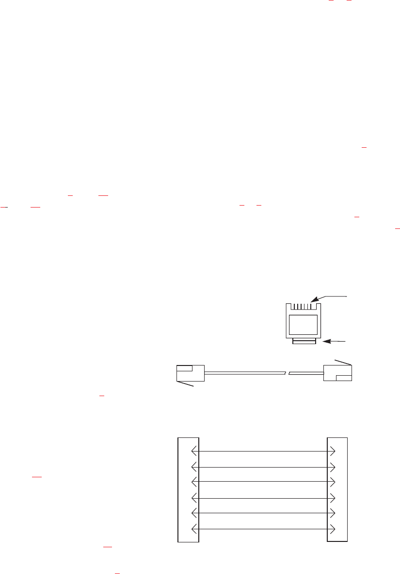
2.5.3 Connection To Intercom System
BKP-4 Connection
Use a standard RTS intercom cable. Either a 9-pin or
RJ12 type can be used. Refer to Figure 5
or 6. Plug one
end of the cable into the appropriate Frame connector on
the back panel of the keypanel. Plug the other end into the
appropriate port of the intercom system. (This will be the
port number that you designated previously when setting
the Address switch.)
☞
Keypanels may be connected while the intercom
system is running.
☞
Note that 9-pin intercom cables for use with an
ADAM CS frame must use special connectors at the
intercom matrix end as described in Figure 6
.
TKP-4 / WKP-4 Connection
You can use either type of standard intercom cable as
shown in Figure 5
or 6. Alternatively, you can connect di-
rectly to the terminal block as shown in Figure 7
. In either
case, use tie wraps to secure the wires as shown in Figure 8
.
12 User Instructions BKP-4, TKP-4, and WKP-4 Keypanels
3 TWISTED PAIR TELEPHONE CABLE
1
2
3
4
5
6
DATA -
1
2
3
4
5
6
AUDIO FROM MATRIX +
AUDIO TO MATRIX -
DATA +
123456
CONTACTS
LATCH
RJ12 MODULAR PLUG
AMP 5-555042-3 or equivalent
(View from cable entrance)
Use AMP Chordal
Crimp Tool
231648-1
or equivalent
PAIR 1: AUDIO TO MATRIX
PAIR 2: AUDIO FROM MATRIX
PAIR 3: DATA
AUDIO FROM MATRIX -
AUDIO TO MATRIX +
Figure 5. RJ12 Intercom cable wiring diagram


