


2 INSTALLATION
2.1 UNPACKING AND INSPECTION
As soon as possible after receipt, inspect the container and
contents for physical damage that may have occurred in
shipping. If damage has occurred, immediately (within 24
hours of receipt of equipment) contact the carrier involved
and file a claim. Save all packing materials, and request
an immediate inspection by the carrier’s insurance claims
agent. The container includes one or more of the follow
-
ing items, depending on the order:
Quantity Description
1 BKP-4, TKP-4, or WKP-4 Keypanel
1 Power Cord (BKP-4 only)
1 User Manual
1 WKP-4 Mounting Box (Optional)
1 AC Power Adapter. Input: 100-240 VAC, 47-63 Hz,
.4A. Output: 15 VDC, 1A max (Optional, used only
for WKP-4 and TKP-4)
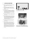
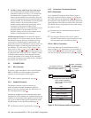
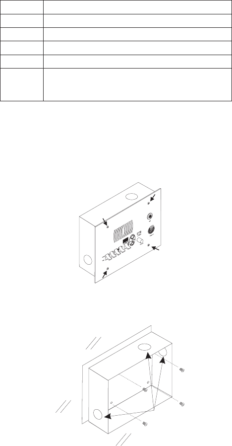
2.2 WKP-4 BOX INSTALLATION
1. If the WKP-4 was supplied assembled to the
mounting box, remove the four (4) screws from the
front panel.
2. Mount the box in a suitable size wall opening using
appropriate mounting screws (not supplied).
3. Route the intercom and power wires into the box.
Reinstall the front panel after all dip switch settings
and connections are completed as described on the
following pages.
☞
If you are not using conduit to route the cables, use a
plastic bushing or similar device at the cable entrance
into the box to prevent abrasion of the wires.
2.3 TKP-4 BOX INSTALLATION
Insert the TKP-4 into a Tektronics equipment bay so that
the spring clips are fully seated.
2.4 CONFIGURATION SWITCHES
☞
Important! If you change any configuration switch
settings during operation, you must momentarily turn
off power to reset.
2.4.1 DIP Switches
DIP Switch 1
Open: Default setting. All incoming calls appear in the
call waiting display (if present).
Closed: Only calls for unassigned callers appear in the
call waiting display (if present).
Description: Any intercom key that is already assigned to
talk/listen to a specific intercom port will always provide
an LED flash for incoming calls from that port. If a desig-
nation strip is used (see Printing Designation Strips, page
15 ) the keypanel operator can identify the caller from the
designation strip. Optionally, the caller's name can also
display in the call waiting window. If you don't want this
to happen, set DIP switch 1 to Close.
☞
The above description applies only to assigned keys.
Whenever there is an incoming call, and there is no
key assigned to the caller, that caller's name will
always display in the call waiting window.
DIP Switch 2
Open: Default setting. 15 second flash after incoming call
is received.
Closed: LED flash until caller releases key.
Description: Whenever there is an incoming call and there
is a talk key assigned to the caller, the talk LED next to
that key will flash. The flash can be set for 15 second
timeout, or until the caller's talk key is released.
DIP Switch 3
Open: Default setting. TIF-951 operation enabled.
10 User Instructions BKP-4, TKP-4, and WKP-4 Keypanels
ALTERNATE CABLE
ENTRANCES