


Chapter 2: Installation
11
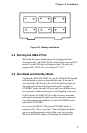
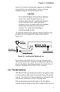
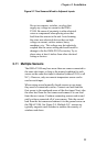
Figure 2-7. Two Sensors Wired to Adjacent Inputs
NOTE
Do not use sensors, switches, or relays that
supply any voltage or current to the OMA-
P1104. Be aware of proximity to other electrical
wires or components when placing wires that
lead from the sensors to the unit. Avoid running
the wires near electrical devices that use high
voltage or current, such as motors, heavy
machinery, etc. This voltage may be inductively
coupled into the sensor wiring and could result in
damage to the the OMA-P1104’s circuitry. Try to
place wires at least 6 inches from other electrical
wiring or devices.
2.11 Multiple Sensors
The OMA-P1104 may have more than one sensor connected to
the same alert input, as long as the normal condition for each
sensor on the same alert input is identical (either all N.O. or all
N.C.). However, only one remote temperature sensor can be
used on each input.
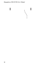
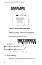
When wiring several normally closed sensors on one input,
they must be connected in series. Connect one lead from the
first sensor to the numbered screw of the alert input. Next, take
the other lead from the first sensor and connect it to one lead
from the next sensor. Continue connecting sensors end-to-end
until you have connected all of your sensors. Take the second
lead from the last sensor and connect it to the ground screw on
the OMA-P1104. See Figure 2-8. Multiple N.C. sensors are
typically magnetic reed switches to monitor the security of
windows and doors.