


5
INSTALLATION
(Continued)
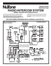
Connecting Antenna
1. Connect the AM/FM antenna (supplied with the IR-104
rough-in) to the 2-pin connector located in the upper right
corner of the main PC board.
In most locations, the antenna supplied with the rough-in
provides adequate AM reception. However, in rural or weak signal
areas a separate AM antenna may be required. Use the following
instructions for selecting and connecting a separate AM antenna.
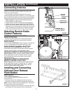
1. Refer to Figure 11. Move the the auxiliary AM antenna
selector switch to the AM position.
2. Connect 50 feet of 22 GA. insulated wire (not supplied by
NuTone) to the screw terminal marked AUX AM ANTENNA.
3. Run the wire from the Master location to the attic. Fasten the
insulated wire at one end of the attic, stretch the wire to its full
length, and fasten at the opposite end. Fasten the insulated
wire at several locations between ends to prevent sagging.
Selecting Remote Radio
Control Features
CONTROLLING THE RADIO FROM
REMOTE STATIONS
The radio may be turned on/off or a stored radio memory
channel may be selected at any remote station as follows:
RADIO ON/OFF
Press and hold the END CALL key for 2 seconds. The radio will
turn on or off depending on the present state of the radio.
RADIO MEMORY CHANNEL SELECTION
Momentarily press the END CALL key. The radio will
sequentially step through the stored radio memory channels.
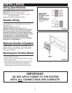
If desired, these functions may be disabled as follows:
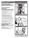
DISABLING REMOTE STATION RADIO ON/OFF
Refer to Figure 12. Slide the switch labeled POWER located
on the master station’s main PC board to the OFF position.
This will disable the remote station radio on/off function at
ALL remote stations.
DISABLING REMOTE STATION RADIO
MEMORY CHANNEL SELECTION
Refer to Figure 12. Slide the switch labeled TUNING located
on the master station’s main PC board to the OFF position.
This will disable the remote station radio memory channel
selection function at ALL remote stations.
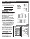
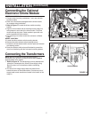
Installing and Connecting
Optional Door Release
Push Button
Refer to Figure 13.
1. Open right-hand panel door.
2. Cut 4 retainer webs from pushbutton hole cover.
3. Remove cover.
4. Feed one wire from Door Release Transformer and one
wire of Door Release mechanism through push button hole.
NOTE: The door release requires a separate 301T Transformer.
5. Connect the 2 wires to the pushbutton.
6. Rotate the pushbutton so the screws are on the top and bottom
as illustrated, then snap the button into the mounting hole.
FIGURE 11
AUXILIARY AM
ANTENNA TERMINAL
SELECTOR SWITCH
ANTENNA
GROUND
AUXILIARY AM
ANTENNA
TERMINAL
AM/FM NOTCH
DIPOLE ANTENNA
CONNECTOR
FIGURE 12
OFF
ON
TUNING
POWER
FIGURE 13