


2
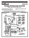
Wiring Specifications
NuTone IW-2: 22 GA. Twisted Pair.
NuTone IWA-3: Flat Ribbon Type 3-wire, 22 GA. cable.
NuTone S-143: 18 GA. 2-conductor insulated.
No. 14/2: 120v, 60Hz Power Cable: Class 1. U.L. Listed
(not supplied by NuTone).
14 GA.: Ground Wire (not supplied by NuTone).
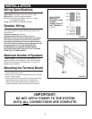
Speaker Wiring
An individual 3-wire cable (IWA-3) must be connected from
each remote speaker or remote control to the master unit’s
terminal board.
• Maximum speaker run: 300 feet.
• Maximum total of IWA-3 per system: 2000 feet.
IMPORTANT: NuTone cannot be responsible for improper
radio-intercom operation that results from interference
generated by light dimmers, fluorescent lighting fixtures,
and similar electrical products. Such interference must be
corrected at the source. TO HELP REDUCE THIS
INTERFERENCE, ALL REMOTE SPEAKER WIRES
AND CABLES MUST BE PLACED AT LEAST 12 INCHES
FROM ANY A.C. POWER WIRING.
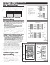
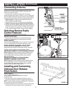
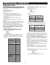
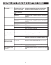
Maximum Number of Speakers
Refer to Figure 1. The System will accommodate up to 13
speakers and up to 3 door speakers. If more than 9 Remote
Stations are connected, use only terminals 1, 2, 6 and 7 for
double wiring connections.
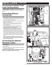
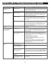
Mounting the Terminal Board
1. Refer to Figure 2. Locate the terminal board in the left rear
section of the rough-in frame.
2. Use four No. 6 x
3
⁄8" screws (supplied) to secure the terminal
board to rough-in frame.
3. Make certain that the lower right screw is secure and snug
against the ground lug which covers mounting hole in
terminal board. Do not bend ground lug. Make sure it is
positioned between mounting screw and terminal board.
FOR SYSTEMS
USING 10-13
SPEAKERS, MAKE
DOUBLE
CONNECTIONS TO
ONLY TERMINALS
1, 2, 6, 7.
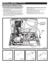
FIGURE 2
RED
SILVER
CENTER
BLUE
COPPER
67
RED
SILVER
CENTER
BLUE
COPPER
GROUND
LUG
1
2
INSTALLATION
FIGURE 1
IMPORTANT:
DO NOT APPLY POWER TO THE SYSTEM
UNTIL ALL
CONNECTIONS ARE COMPLETE.