


3
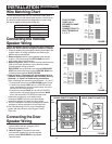
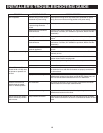
Wire Matching Chart
NuTone has adopted the use of a 3-wire color-coded cable. If
you are replacing an older model radio-intercom, use this chart
to match the copper/center/silver designations of older wiring
with the blue/grey/red-stripe color-coded wire.
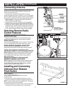
Connecting the Remote
Speaker Wiring
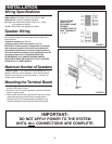
NOTE: All speaker and door wiring must return directly to
Master unit. Do not connect wiring from speaker to speaker.
1. Dress all speaker wiring through the oblong wire holes in the
rough-in frame. All wiring connections are made to the
Master unit’s terminal board.
2. Refer to Figure 6. When routing speaker wires through
rough-in, run wires through the LEFT-HAND side of the
upper and/or lower wiring channels.
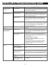
3. Refer to Figures 3, 4 & 5. Connect the three-conductor wire
(IWA-3) from each speaker to a set of terminal screws.
Connect speaker wiring as follows:
RED STRIPE wire to terminal screw marked RED SILVER.
GREY wire to terminal screw marked CENTER. BLUE wire
to terminal screw marked BLUE COPPER.
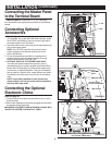
4. Refer to Figure 5. The system will accommodate up to 13
speakers. If more than 9 speakers are connected, use only
terminals 1, 2, 6 and 7 for double wiring connections.
When connecting two remotes to screw terminals 1, 2, 6 and 7.
• Connect both red wires to the RED SILVER terminal screw.
• Connect one remote’s GREY wire to a CENTER terminal
screw, and connect the second remote’s center wire to the
second CENTER terminal screw.
• Connect one remote’s BLUE wire to a BLUE COPPER
terminal screw, and connect the second remote’s BLUE
wire to the second BLUE COPPER terminal screw.
Repeat this procedure for each double remote
connections. NOTE: Failure to make these double
connections properly will cause the unit to squeal.
5. Refer to installation instructions packaged with remote
speakers or remote controls for wiring of the units.
6. See “Wire Matching Chart” if you are retrofitting a
system with the previously used Copper/ Center/
Silver wire.
OLD CABLE NEW CABLE
Wire Insulation
Copper Blue
Center Grey
Silver Red Stripe
RED
SILVER
CENTER
BLUE
COPPER
RED
SILVER
CENTER
BLUE
COPPER
RED
SILVER
CENTER
BLUE
COPPER
RED
SILVER
CENTER
BLUE
COPPER
EARTH
DOOR
SPKR
RED
STRIPE
GREY
BLUE
RED
STRIPE
SINGLE REMOTE CONNECTION
DOUBLE REMOTE CONNECTION
GREY
BLUE
TERMINAL BOARD
RED
SILVER
1
CENTER
BLUE COPPER
1234
6789
5
CN702
CN701
CN703
CN704
1
2
6
7
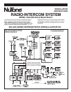
INSTALLATION
(Continued)
FIGURE 4
FIGURE 3
FIGURE 5
FOR SYSTEMS
USING 10-13
SPEAKERS, MAKE
DOUBLE
CONNECTIONS TO
ONLY TERMINALS
1, 2, 6, 7.
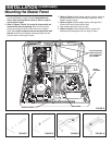
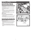
Connecting the Door
Speaker Wiring
1. The door speaker connects to the Master
terminal board with two conductor (IW-2)
22 gauge twisted pair wire.
2. Refer to Figure 4. Connect the two wires
from the door speaker(s) to the two terminal
screws marked DOOR SPKR on the Master
Te r minal board.
RED
SILVER
CENTER
BLUE COPPER