


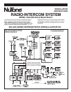
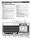


11
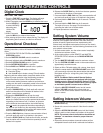
OPERATIONAL CHECKOUT
The following diagnostic test have been incorporated into
the NuTone IMA-3303 Radio Intercom to assist in system
troubleshooting.
1. Master station keyboard test
2. Control line voltage test
3. Display test
The following applies to all three diagnostic tests:
1. To access any of the diagnostic tests, the system must
be in the quiescent state (radio off and intercom in the
standby mode).
2. Pressing the MEMORY SET key will end the current
diagnostic test.
3. The current diagnostic test will end after one minute of
inactivity.
NOTE: An incorrect control line voltage caused by miswiring
or a defective remote station may prevent the unit from entering
the diagnostic mode. This condition, however, can
be circumvented by first placing all station selector switches
into the OFF mode and then disconnecting CN701 from the
terminal board. The voltage on the control line can then be
measured by activating the control line voltage test mode and
then reconnecting CN701.
1. MASTER STATION’S KEYBOARD TEST – Verifies that
all keys on the master station are functioning properly.
To Activate: Press and HOLD
1. ▲ key
2. ▼ key
3. MEMORY 1 key.
In this mode the hours in the display represent the current
diagnostic test and the minutes indicate the current key
being pressed. The following will be displayed as each key
is pressed.
2. CONTROL LINE VOLTAGE TEST – Displays the voltage
on the control line.
To activate: Press and HOLD
1. ▲ key
2. ▼ key
3. MEMORY 2 key.
Example:
In this mode, the hours represent the diagnostic test,
and the minutes indicate the voltage on the control line.
The control line voltage windows for the three intercom modes
are listed above. For proper intercom operation, the control
voltage produced when an intercom key is pressed at a remote
station should fall between the voltages indicated.
NOTE: Pressing END CALL, DOOR TALK or INSIDE/PATIO
keys at the master station will not change the voltage on the
control line.
If a remote station does not produce a voltage within the above
windows for a specific intercom function, check the following:
• Make sure all connectors from the master station are properly
installed into the terminal PC board.
• Check IWA-3 connections at the terminal PC board and at
each remote station.
• Confirm that the suspect remote speaker station functions
properly by replacing it with a known good Remote Station.
3. DISPLAY TEST – Displays all of the segments in the display.
To Activate: Press and HOLD
1. ▲ key
2. ▼ key
3. MEMORY 3 key
Pressing the ▲ key toggles the display on and off.
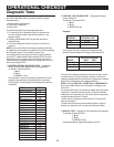
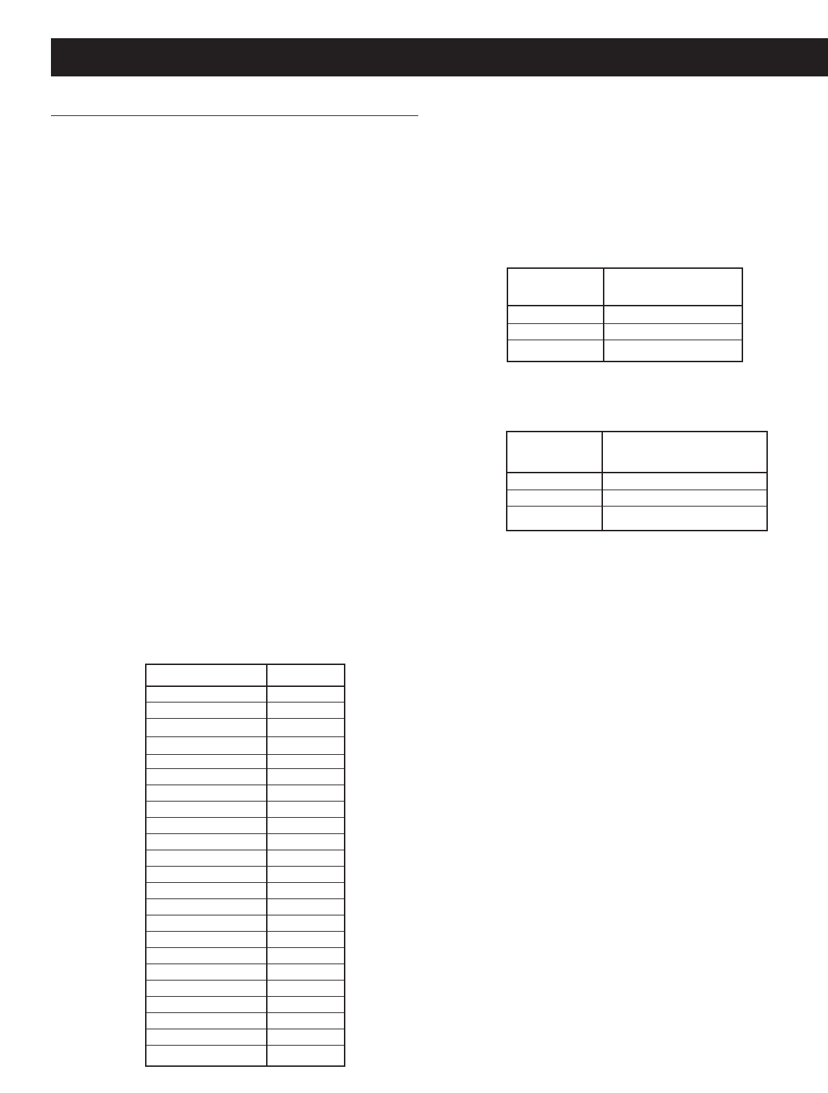
Diagnostic Tests
KEY DISPLAY
No key pressed 1:00
SCAN 1:01
▲
1:02
▼ 1:03
PROGRAM OFF 1:04
AM 1:05
FM 1:06
CD/TAPE 1:07
AUX 1:08
TIMER 1:09
INSIDE/PATIO 1:10
DOOR TALK 1:11
END CALL 1:12
MEMORY 1 1:13
MEMORY 2 1:14
MEMORY3 1:15
MEMORY 4 1:16
MEMORY 5 1:17
MEMORY 6 1:18
TIME SET 1:19
HOUR 1:20
MIN 1:21
MEMORY SET
1:22
VOLTAGE ON
DISPLAY CONTROL LINE
2:34 3.4 volts
2:17 1.7 volts
2:06 .6 volts
VOLTAGE WINDOW
MODE MAX MIN
End Call 4.5V - 2.4V
Door Talk 2.4V - 1V
Inside/Patio 1.0V - 0
11