


4
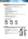
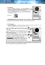
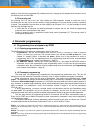
2.1.2 Uncover control elements
4. Push the aluminium speaker grille down (see figure – 4).
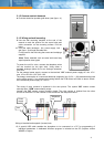
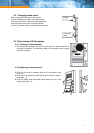
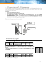
2.1.3 Wiring and wall mounting
5. Use the wall mounting template at the end of the
manual to mark the position for the screw holes and
cable connection on the mounting surface. Drill the
holes.
6. Feed the cable (analogue line, power supply, lock –
see figure - 6) through the cable hole.
Fix the panel to the wall using the screws and rawlplugs
supplied.
Note: Some materials such as metal and wood may
require special screw types.
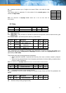
To power the unit for voice, connect the telephone wires
into the terminal (on the right side). Using either a
standard analogue phone line or an analogue extension
on a PBX.
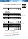
For the external power supply, connect to the terminal "12V" external power supply AC min. 10V /
max. 15V or DC min. 12V / max. 18V.
The energy consumption of a connected electrical (magnetic) lock (0,5A – 1,0A) determines the load
on the power supply. If you activate the heating feature the PCB current will climb to about 150mA.
We recommend power supply AC 12V/1A.
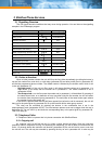
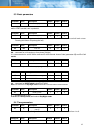
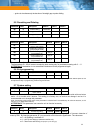
The wiring of relay contacts is explained in the next picture. The symbol "NO" means contact
normally open, "COM" means sharing output
(central) and "NC" means contact normally closed. The relay contact is isolated from the other
circuits on the board. For the variants of lock connection see the picture below.
Wiring of standard and magnetic (inverse) lock
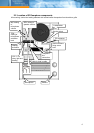
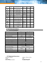
6. A special USB cable enables the doorphone to be connected to a PC for programming of
individual parameters. A dedicated Windows program is included on the CD (requires version
W98SE or higher).
Power
su
pp
l
y
lock
Telephone
line