


6
Installation (Continued)
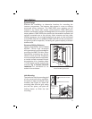
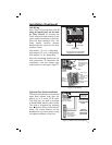
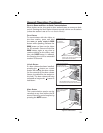
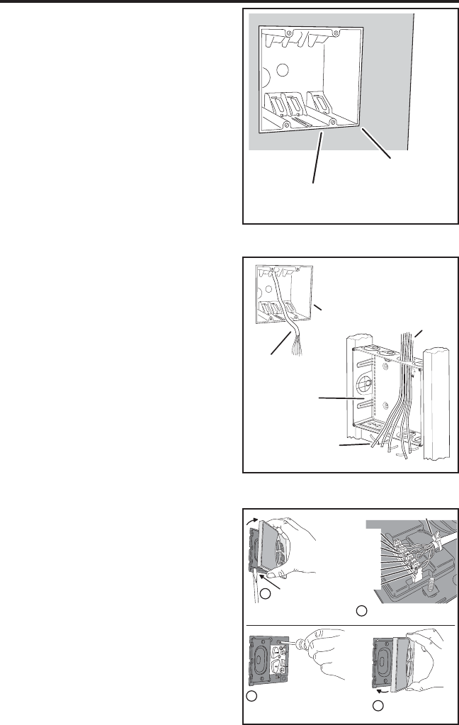
Junction Box Installation
Each intercom station mounts inside
a standard 2-gang J-box. Mount the
J-boxes fl ush with the drywall at
locations and heights convenient
for the installation.
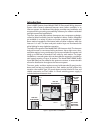
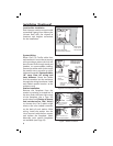
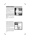
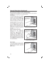
System Wiring
Route Cat-5 or Cat-5e cable from
each station’s J-box to the structured
wiring enclosure where the hub will
be mounted. Drill through studs and
headers to accommodate cabling.
Secure the cables with zip-tie straps
(be careful not to puncture or pinch
cables with staples). Route all cables
18” away from AC wiring and
lamp dimmers. Route the cables
from the stations into the enclosure
through the wiring knockouts. Label
each cable’s station location at the
enclosure end.
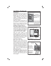
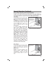
Station Installation
Remove the faceplate from the
station by twisting a screwdriver in
the slot under the lower left corner
of the faceplate. Use a Type 110
punch-down tool (if using an impact
tool, set the tool to “low” force!)
to connect the Cat-5 cable’s eight
wires to the color coded connector
on the back of each station. After
wiring, install the station into the
J-box, secure it with the four screws,
and replace the faceplate. Note:
Alternate color station faceplates
are available (see Page 18).
MOUNT 2-GANG J-BOX
AT EACH STATION LOCATION
MOUNT J-BOX
FLUSH TO THE
WALL SURFACE
Figure 5. Junction Box Installation
Figure 6. Pre-wiring Cat-5 Cable
LABEL STATION
LOCATIONS
ON CABLES
CAT-5 CABLES
FROM STATIONS
STATION
J-BOX
CAT-5 CABLE
TO ENCLOSURE
STRUCTURED
WIRING
ENCLOSURE
MAXIMUM WIRE RUN:
500 FEET OF CAT-5 CABLE
FROM EACH STATION
TO THE ENCLOSURE
Figure 7. Station Installation
1
TWIST SCREWDRIVER
IN SLOT TO REMOVE
FACEPLATE
2
USE TYPE 110 PUNCH DOWN
TOOL TO CONNECT CABLE
BLUE STRIPE
BLUE
ORANGE STRIPE
ORANGE
GREEN STRIPE
GREEN
BROWN STRIPE
BROWN
ZIP-TIE CABLE
3
4
INSTALL STATION IN J-BOX
DO NOT OVER-TIGHTEN SCREWS!
SNAP FACEPLATE
ONTO STATION