


TK-8180
46
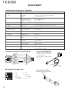
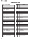
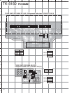
Display unit (X54-3480-10)
Pin No.
Name Description
CN901 (to internal speaker)
1 GND Ground.
2 SPO Speaker output.
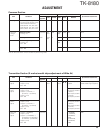
CN902 (to TX-RX unit B/3 CN429)
1 SPO Speaker input.
2 SPO Speaker input.
3 SPO Speaker input.
4 SPO Speaker input.
5 SPO Speaker input.
6 SPO Speaker input.
7 GND Ground.
88C 8V input.
9SB Power input of switched power supply.
10 SB Power input of switched power supply.
11 NC Non-connenction.
12 PSW Detection signal output of power switch.
13 GND Ground.
14 GND Ground.
15 MIC MIC signal output.
16 ME MIC ground.
17 GND Ground.
18 PSENS Detection signal output of display unit.
19 RST2 Reset signal input.
20 GND Ground.
21 GND Ground.
22 GND Ground.
23 NC Non-connenction.
24
SHIFT/MODEL
Control signal input of beat-shift function.
25 NC Non-connenction.
26 5C 5V output.
27 TXD Serial data signal input.
28 RXD Serial data signal output.
29 GND Ground.
30 GND Ground.
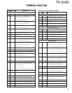
J901 (MIC jack)
1 BLC MIC backlight control.
2SB DC 13.6V±15%, 200mA typ.
3E Ground.
Pin No.
Name Description
4 PTT/TXD PTT : PTT input, TXD : Serial data output.
5ME MIC ground.
6 MIC MIC signal input.
7
HOOK/RXD
HOOK : Hook detection, RXD : Serial data input.
8DM MIC data detection.
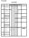
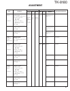
TX-RX unit (X57-6990-10) (A/3)
Pin No.
Name Description
CN701 (to TX-RX unit B/3 CN427)
1 AUXIO6 AUX input/output 6.
2 AUXIO7 AUX input/output 7.
3 AUXIO1 AUX input/output 1.
4 AUXIO2 AUX input/output 2.
5 RXD2 Serial data output 2.
6 AUXIO3 AUX input/output 3.
7 TXD2 Serial data input 2.
8 AUXIO4 AUX input/output 4.
9 AUXIO8 AUX input/output 8.
10 AUXIO5 AUX input/output 5.
11 AUXIO9 AUX input/output 9.
12 AUXO1 AUX input 1.
13 TXD1 Serial data input 1.
14 AUXO2 AUX input 2.
15 RXD1 Serial data output 1.
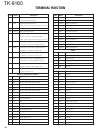
16 GND Ground.
17 ME MIC ground.
18 MI2 External MIC output.
19 DEO Detected signal input.
20 GND Ground.
21 5C 5V.
22 DI Data signal output.
23 AFO RX filtered audio input.
24 SB Power input after power switch.
25 SB Power input after power switch.
26 SB Power input after power switch.
27 SB Power input after power switch.
28 SB Power input after power switch.
29 SB Power input after power switch.
30 NC Non-connenction.
TERMINAL FUNCTION