TK-8180
12
CN1
CN403
GPS receiver
VGS-1
8-2.
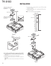
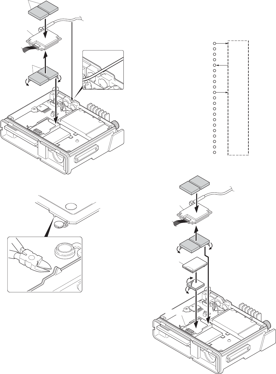
Installing the GPS receiver together with the VGS-1
1. Remove the cabinet, top packing and shielding plate of the
transceiver.
2. Remove the front panel from the transceiver.
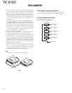
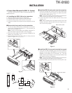
3. Attach a cushion to the bottom of the VGS-1 as shown in
Figure 8-5.
Note : Be sure not to cover the connector with the cush-
ion.
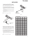
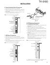
TX-RX unit (B/3)
Solder land
GND (GND)
RXD1
TXD1
TXD2
RXD2 (DATA OUT1)
OPT1
OPT3
OPT4
OPT5
5E (+5V)
DTI
TCTL
TXO
AUDIH
OPT2
STON
RXEO
TXI
RXEI
OPT6
8C
GPS receiver
3M Double coated cushion
No. 4016 (or No. 4416)
30 x 25 mm
3M Double coated cushion
No. 4016 (or No. 4416)
30 x 25 mm
GPS receiver
q
w
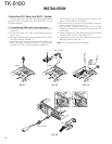
Fig. 8-2
Fig. 8-3
Fig. 8-4
Fig. 8-5
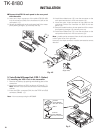
4. Insert the VGS-1 connector (CN1) into the TX-RX unit (B/3)
connector (CN403).
5. Perform step 3 to 6 of “8-1. Installing the GPS receiver”
described on page 11.
Note : You must setup using the KPG-89D.
INSTALLATION


