


TK-8180
13
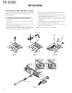
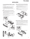
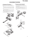
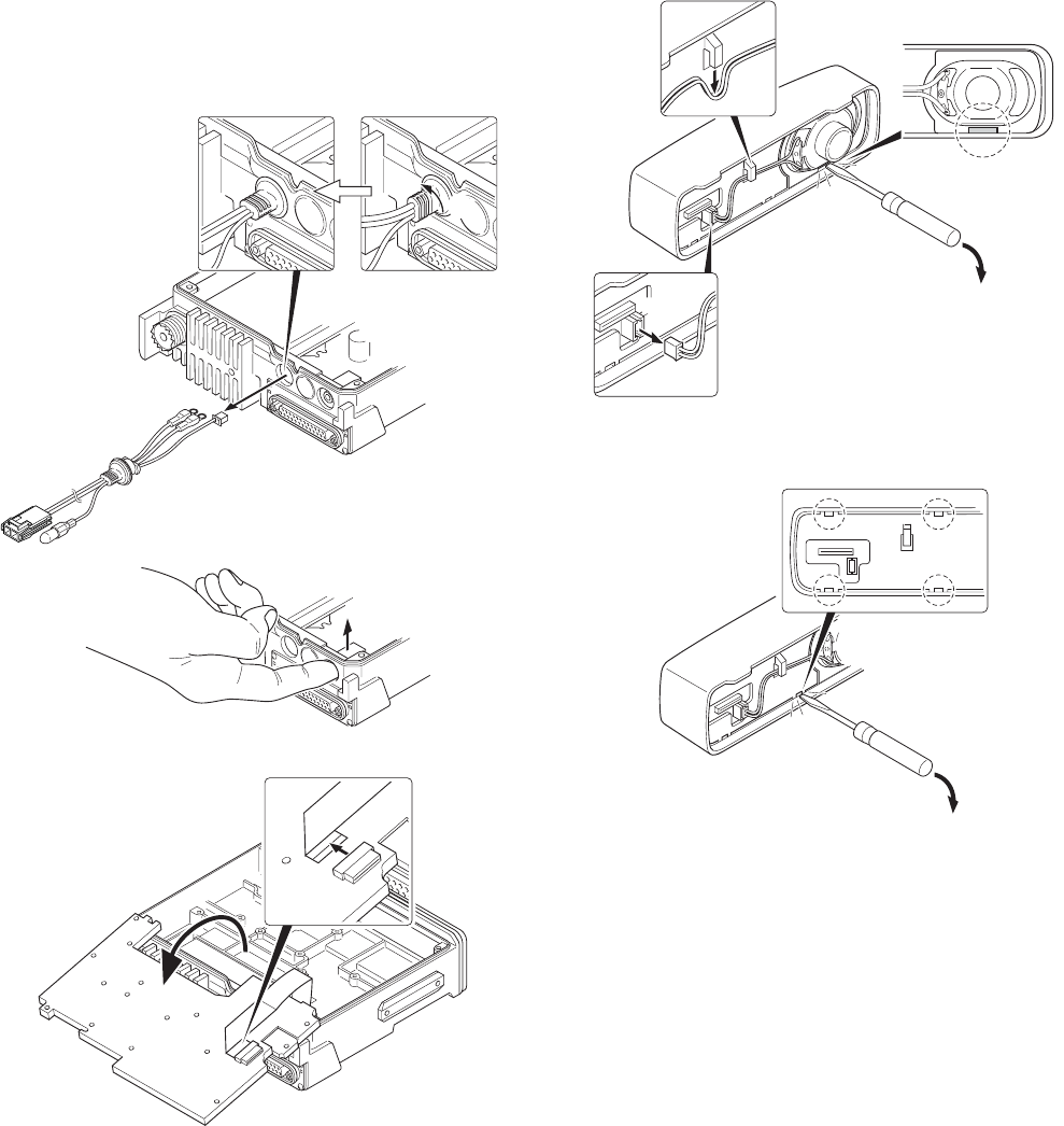
■ Removing the speaker hardware fixture
(J21-8481-03) and holder (J19-5468-03)
1. Remove the speaker lead from the holder hook. ( q )
2. Remove the speaker connector from the display unit con-
nector (CN901). ( w )
3. When removing the speaker hardware fixture, insert a flat-
head screwdriver at the position shown in Figure 2-1 and
tilt it in the direction shown by the arrow. ( e )
4. To remove the holder, insert a flat-head screwdriver into
tab of the holder and tilt it in the direction shown by the
arrow. ( r )
CN901
w
q
e
r
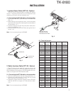
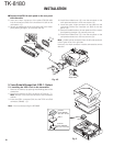
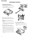
1. Precautions on Disassembly
■ TX-RX PCB (TX-RX unit B/3) Disassembly
1. Remove all screws and antenna terminals on the TX-RX
PCB.
2. Rotate the bush of the power supply cable 90 degrees
counterclockwise as viewed from the rear of the chassis
( q ) and remove the power supply cable from the chassis
( w ).
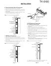
3. When the speaker phone jack is pushed up, using your
finger, from the rear of the chassis ( e ), the TX-RX PCB is
removed from the chassis.
Note : The TX-RX PCB and D-sub PCB (TX-RX unit A/3) are
connected with a flat cable. Remove them carefully.
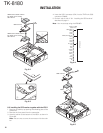
4. Turn the TX-RX PCB over and remove the flat cable from
the connector (CN427). ( r )
5. Remove the TX-RX PCB from the chassis.
q
w
e
CN427
r
Fig. 1-1
Fig. 1-3
Fig. 1-2
Fig. 2-1
Fig. 2-2
DISASSEMBLY FOR REPAIR