


ADDENDUM TO ISSUE 4 OF THE AXXESS MANUALOCTOBER 1997
Page 38 of 73
DKSC-16 Extended Loop Length
Modification
For longer station loop lengths (up to 154 ohms/3000
ft.), if necessary, an optional external power supply
with the following characteristics can be connected to
the DKSC-16 termination block:
•
36VDC
•
120mA per keyset (1.92A for all 16 circuits)
This option is available only on DKSC-16s that are at
revision level “2.0” or later or that have been modified
and labeled with FSM100995. The external power sup-
ply is connected to pins 50 (+36V, V/SL) and 25 (GND,
SL/V) on the termination block. In addition, the strap
on jumper JP1 must be placed over pins 1 and 2 to en-
able the external power supply.
New Voice Processing Card (VPC)
Models
The 4-Port and 8-Port VPCs described in the Issue 4
manual have been superseded by newer “mini-size”
models. Other than their smaller size, these new mini-
size cards install and function the same as the original
full-size cards. The part numbers of the new cards are
listed in the following table.
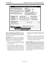
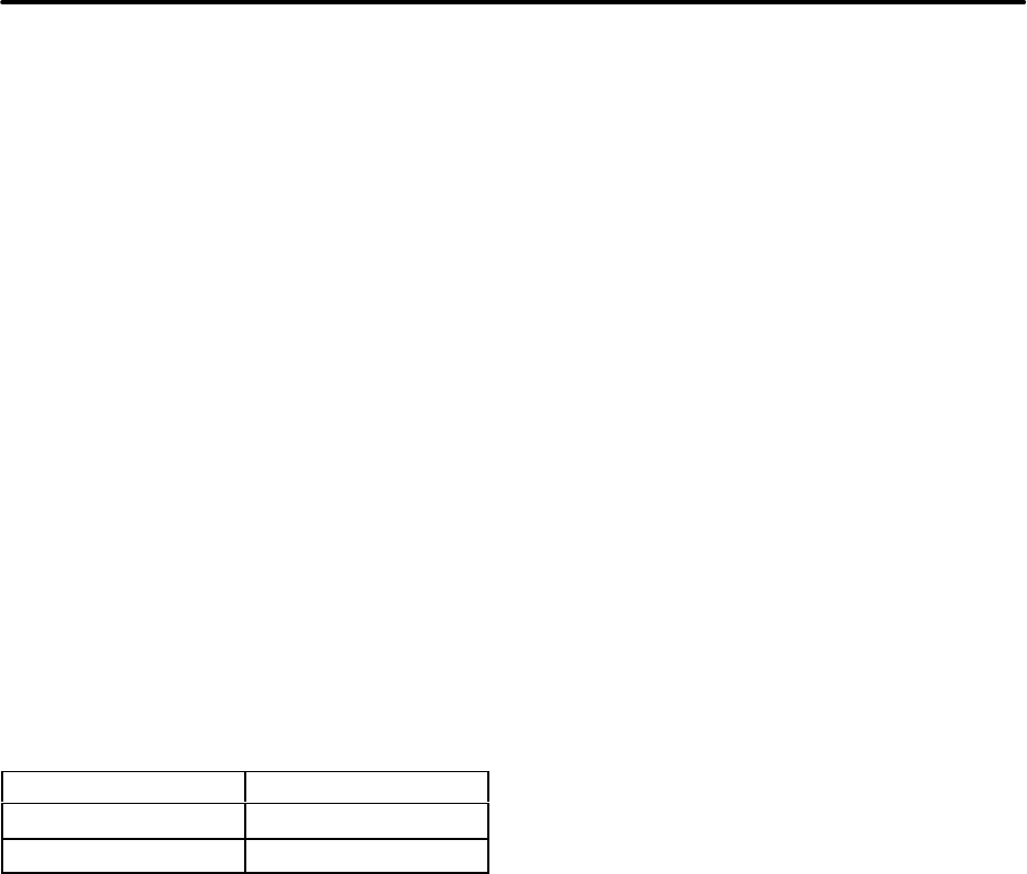
NEW VPCs PART NUMBERS
4-Port “Mini” VPC 550.5209
8-Port “Mini” VPC 550.5210
CPU020/PCM Card Software Installation
Information
The following information will be useful when loading
CPU 512 Master and Slave software.
New Warning Message: A warning message will now
appear if you attempt to load CPU 512 Master software
without a CPU 512 Slave Card installed and communi-
cating. The message says, “WARNING, the Slave CPU
is off-line. Uploading code without a Slave CPU may
cause serious system problems. Do you wish to contin-
ue with the upload?” You can continue the upload by
selecting Yes or abort the upload by selecting No. (If
you select Yes, you must install software on the CPU
512 Slave Card before it will function. Refer to page
3–73 in the manual for details.)
Checking Validity of Software On A Slave CPU:
You can use the following procedure to check the
validity of software on your CPU 512 Slave Card:
(1) Attach a terminal (or a PC using terminal emu-
lation software) to the serial port on the secon-
dary CPU in slot 24. (Communication parame-
ters are: 9600 baud, no parity, 8 bits, 1 stop bit.)
(2) Turn off the secondary cabinets (slots 17–31).
(3) Turn on the secondary cabinets while watching
the power-up messages on the terminal. You
should see:
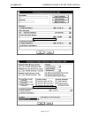
Boot Version 4.0 (827.8536 U25, CPU020-EXP, Slave)
AXXESS 4.
x
Call Processing Quad
(4) If you do not see the correct information, upload
the version 4.X Premium software from the pro-
gramming PC to the CPU020/PCM Card as out-
lined on page 3–73 in the manual.
New FCC Part 68 PBX Rating
The AXXESS System is now officially rated as a PBX
system by the FCC. The official registration number is:
BE2USA–24359–PF–E. This means the AXXESS Sys-
tem now carries all three ratings: KF (key system), MF
(hybrid system), and PF (PBX system).
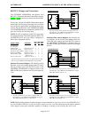
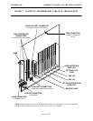
New Fax Card Model
The optional Fax Card described in the Issue 4 manual
has been superseded by a newer model. (Note that the
part number for the new model card remains 550.5122).
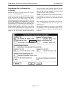
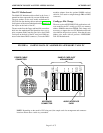
If installing one of these newer model cards (which can
be identified by the drawing on page 40), use the in-
structions outlined below in place of step 8 on page
3–108 in the manual.
(1) If desired and if not already installed, install the
optional Fax Card as follows (refer to drawing
on page 40):
a. Remove the bracket that covers the opening
to the appropriate 16-bit (full-size) slot, and
set the bracket and screw aside. (Refer to
Figure 3–57 on page 3–111 in the manual for
a sample card slot arrangement.)
b. Check to make sure that a jumper strap is
placed over the middle two pins (IRQ9) of
interrupt jumper J503 (refer to drawing on
page 40).
c. Ensure that the eight address selection DIP
switches (SW1) are set to 320 hex: 1–3 &
5–6 = ON (down); 4 & 7–8 = OFF (up).
d. Check to make sure the two MVIP clock ter-
mination DIP switches (SW2) are set in the
OFF (up) position.