


4 Technical Services: 800-283-5936
CHAPTER 2: INSTALLATION
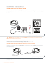
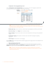
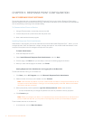
CONNECTING YOUR CONFERENCE PHONE
Connect the Connection cable from the Link Out jack on the base unit to the Link In jack on the conferencing pod
(see figure 2.1).
Warning: DO NOT plug a laptop or PC into the Link Out jack on the base unit or conferencing pod as
severe electrical damage could occur.
Connect the base unit to the Ethernet jack using the Ethernet cable.
Connect the power cord to the base unit and plug it directly into an electrical outlet.
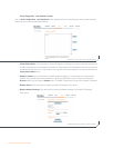
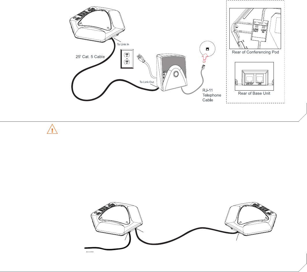
CONNECTING ADDITIONAL MAX IP RESPONSE POINT PHONES
Connect the 12’ Connection cable to the Link Out jack on the first phone and to the Link In jack on the second
phone (see figure 2.2).
12' Connection cable
From Link Out
To Link In
To Link In
To Link Out on Base Unit
25' Connection cable
Continue linking additional MAX IP Response Point phones in the same fashion. A total of four units may be
connected.
Figure 2.1 Connecting the MAX IP Response Point
Figure 2.2 Connecting additional units