Equipment Upgrades
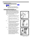
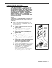
Adding New Modules
1
A)
B)
C)
2
A)
B)
3
A)
B)
Power
Jack
Handle
Tab
4
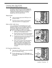
To power down the control unit, pull out the
main circuit breaker.
On a PARTNER Plus 220V system, move the
on/off switch to the “off” position (“O”).
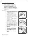
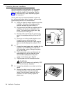
To remove the cover, place one hand on the
handle on the bottom front of the cover and
place your other hand on the top of the cover.
Gently pull the cover up from the bottom and tilt
it towards the top until it detaches from the
backplane.
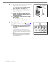
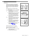
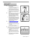
Before you insert the new module, make sure that
all 400 (or 200) modules are installed to the
right of all 206 modules. Also, remember to
hold down the locking tab and to align the
dovetail guides on the sides of the modules
as you insert the new module.
Push the module slowly but firmly until it locks
into place with two snaps, and is attached to
the rear of the backplane and held in place by
the locking tab on the bottom of the slot. Do
not force the module. If it does not insert
easily, remove the module, clear any
obstruction, and reinsert.
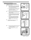
See “Connecting Lines and Extensions” for
instructions on connecting line and/or
extension jack cords to the new module.
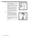
To power up the control unit, push in the main
circuit breaker.
On a PARTNER Plus 220V system, move the
on/off switch to the “on” position (“l”).
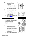
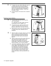
Check all green lights on the fronts of the modules. If
all the lights are lit, installation is complete; otherwise:
A)
If a single light is out, power down the control
unit, reseat the module, then power up the
control unit.
If multiple lights are out, power down the
control unit, reseat the first leftmost module
that has a light out, then power up the control
unit.
B)
If the lights are still out, call the appropriate
support telephone number as instructed on
the inside front cover.
Main
Circuit Breaker
Dovetail
Guides
Locking
Lights
Equipment Upgrades
17


