


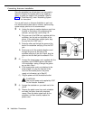
Connecting Lines and Extensions
If extensions are not wired to any modular jacks, call a
qualified service technician.
555-1343
1
2
3
4
555-1344
A)
B)
C)
A)
B)
C)
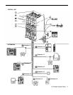
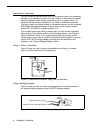
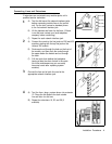
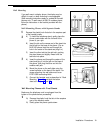
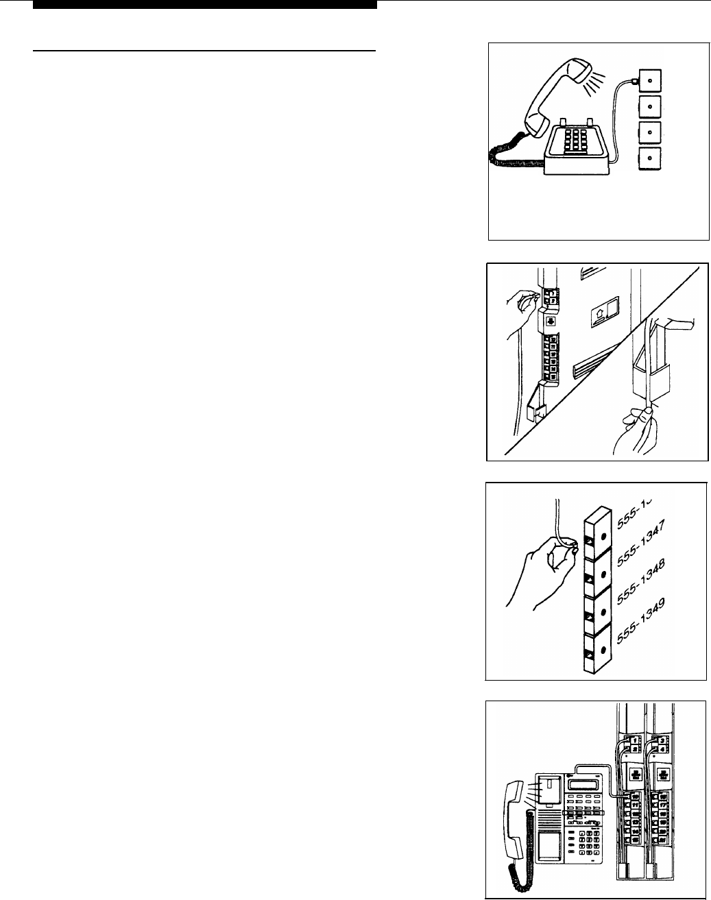
Test for dial tone at the network interface jacks
before connecting outside lines to the control
unit. For the test, connect a standard phone
to the first network interface jack.
Lift the handset and listen for dial tone. (If there
is no dial tone, contact your local telephone
company before continuing.)
Repeat for each network interface jack.
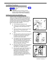
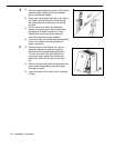
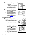
Connect line cords to the line jacks on 206 and 400
555-1345
555-1346
Network
Interface
Jacks
modules, starting with the top line jack on the
leftmost 206 module.
Route each cord through the hook on the front of
the module, and then push the cords through
the space below the module and out through
the back.
Pull the cords from behind the backplane,
leaving at least two feet of slack in the cords
(for future maintenance so you can easily
reconnect cords after replacing system
modules).
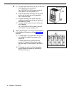
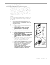
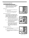
Connect the free end of each line cord to the
appropriate network interface jack.
A)
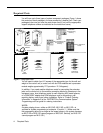
Test the lines—plug a system phone into extension
10. Press the line buttons for each outside
line and listen for dial tone.
B)
Repeat for extensions 16, 22, and 28 (if
available).
Installation Procedures
9