


Installation Procedures
Before installing the system, be sure you read the safety
instructions on page ii.
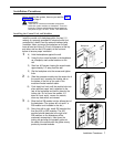
WARNING:
There are no customer-serviceable components
inside the system modules or backplane. There are
hazardous voltages within that can cause severe or
fatal personal injury. DO
NOT OPEN THE MODULES.
Installing the Control Unit and Modules
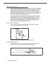
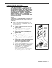
Install the control unit’s backplane within five feet (1.5
meters) of a properly grounded AC electrical outlet (not
controlled by a switch) and the network interface jacks.
In addition, when you mount the backplane on the wall,
leave at least six inches (2.34 cm) of clearance at the top
and sides, and two feet (0.6 meters) at the front and
bottom to ensure proper ventilation.
1
2
3
A)
B)
C)
D)
A)
B)
A)
B)
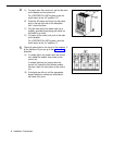
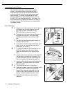
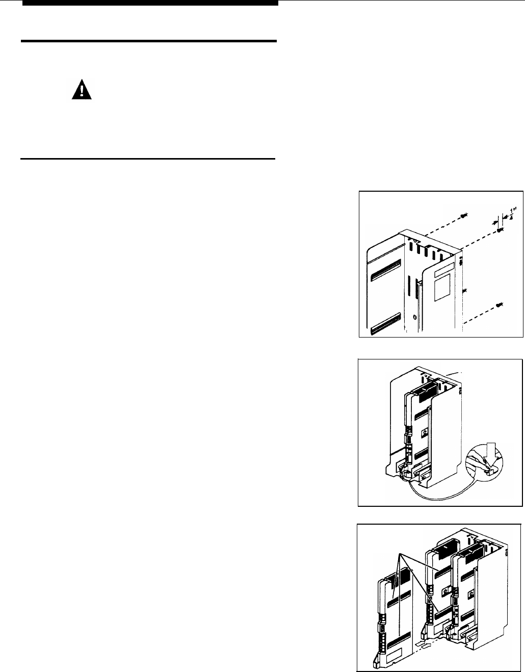
Hold the backplane against the wall.
Using the four screw keyholes in the backplane
as a template, mark screw locations on the
wall.
Start four #12 screws, leaving the screw heads
approximately 1/4” away from the wall.
Slip the backplane onto the screws and tighten
them.
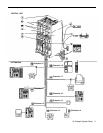
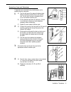
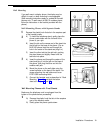
Slide the processor module into the center slot of
the control unit—pressing the locking tab on
the bottom of the slot as you push in the
module will make insertion easier.
Push slowly but firmly until the module locks into
place with two snaps, and is attached to the
rear of the backplane and held in place by the
locking tab. Do not force the module. If it
does not insert easily, remove the module,
clear any obstruction, and reinsert.
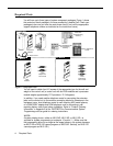
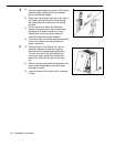
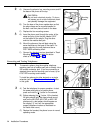
Slide the first 206 module into the leftmost slot of
the backplane. (The system will not work if a
206 module is not installed in this slot.)
Going from left to right, install 206 modules first,
then any 400 (or 200) modules. The 400
modules should always be to the right of all
206 modules, so the extensions will be
numbered consecutively. Hold down the
locking tab and align the dovetail guides on
the sides of the module with the guides on any
previously inserted modules.
Backplane
Backplane
Locking
Tab
Dovetail
Guides
Installation Procedures
7