Network Turnup Procedure Total Access 600 Series System Manual
38 © 2004 ADTRAN, Inc. 61200624L1-1B
5. MOUNTING OPTIONS
All units may be wallmounted or installed in a table-top application. In addition, the Total Access 612/616/624
units are available for 19- or 23-inch rackmount installations. Wallmount brackets are included with the unit
and are already attached. For a rackmount installation, optional rackmount brackets must be purchased (19” –
P/N 1200627L1, 23” – P/N 1200627L2).
Wallmounting the Unit
Tools Needed
The unit mounts and connects with standard fasteners and hand tools:
• Four #8 x 3/4-inch pan-head wood screws
• Drill and drill bit set
• Flat head screwdriver (medium)
• Two Phillips head screwdrivers (small/medium)
• Wire-wrap gun (optional)
• 25-pair male amphenol cable (customer connection)
• Selected punch-down block and tool
Follow these steps to wallmount the unit:
Be careful not to upset the stability of the equipment mounting rack when installing this
product.
Wallmount Installation
Step Action
1. Decide on a location for the unit. Keep in mind that the unit needs to be mounted at or below
eye-level so that the LEDs are viewable.
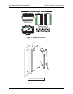
IMPORTANT! Mount the chassis with LEDs facing to the side or down as shown in Figure 1 on
page 39 (not facing up).
Refer to Figure 2 on page 39 for a wallmount illustration.
2. Prepare the mounting surface by attaching a board (typically plywood, 3/4” to 1” thick) to a wall
stud.
IMPORTANT! Mounting to a stud ensures stability. Using sheetrock anchors may not provide
sufficient long-term stability.
3. Have someone else hold the unit in position as you install two #6 to #10 (1 1/2” or greater in
length) wood screws through the unit’s brackets and into the mounted board.
4. Proceed to the steps given in Supplying Power to the Unit on page 40.


