


6
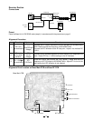
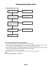
Receiver Section
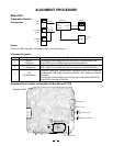
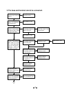
Connections
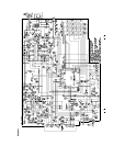
Alignment Point Location on Handset Main PCB and Handset RF PCB
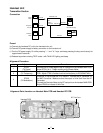
Preset
a) Connect the handset RF unit to the handset main unit.
b) Connect DC power supply to battery connector on the handset unit.
c) Turn the DC power supply ON while pressing “
æ
” and “ # ” keys, and keep pressing the keys continuously for
approximate 2 seconds.
d) Release keys when entering TEST mode 1 with TALK LED lighting and beep.
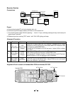
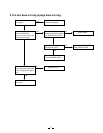
Alignment Procedure
step
1
2
3
Preset to
SG: 1mV
No modulation
SG: 1mV
1 kHz ±8kHz
deviation
SG: -6.0 dB
µ
V
1kHz ±8kHz
Deviation
Remarks
Press the “4” key to enter the TEST Mode 4. Connect the RF Singal
Generator to the RF test point on the handset MAIN PCB. Make sure that
the frequency is 926.997467 MHz.
Connect the DC Voltmeter to the AF test point. Adjust L602 to indicate
DC 1.00 V.
Connect the RF Signal Generator to the RF test point on the handset MAIN
PCB. Make sure that the frequency is 926.997467 MHz.
Connect the AC Voltmeter across a 150-ohm dummy to the SP Terminal.
Adjust RT602 for a 130 mV reading on the AC Voltmeter.
Press the “5” key to enter the TEST Mode 5. Make sure that the frequency
of RF SG output is 926.997467 MHz. Adjust RT601 to turn to the point
where the indication is just vibrated.
Adjustment
L602
(Discriminator
Voltage)
RT602
(RX AF
Voltage)
RT601
(SQ Point)
AC VoltmeterHANDSET Unit
AF
Test Point
Dummy Load
(150-ohm)
RF SG
DC 3.8V
J601
Battery
Connector
BLK
RF
Test Point
SP
Terminal
DC Power Supply
DC Voltmeter
WHT
+
-
RF PCB
RF Test Point
L602
RT602
J601
RT601
AF Test Point
Handset PCB
SP Terminal
WHT
BLK