


3
ALIGNMENT PROCEDURE
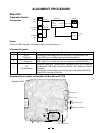
Base Unit
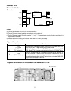
Transmitter Section
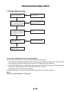
Connections
Preset
Press the “PAGE” key about 3.0 seconds while truning the power on.
Alignment Procedure
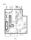
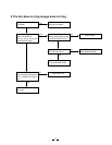
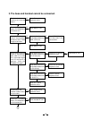
Alignment Point Location on Base Main PCB and Base RF PCB
step
1
2
3
Adjustment
RT301
(TX Power)
CT1
(TX Frequency)
RT3
(TX Modulation)
Remarks
Connect the Power Meter to the RF test point on the Base MAIN PCB.
Adjust RT301 for a -8.5dBm reading on the Power Meter.
Connect the Frequency Counter to the RF test point on the Base MAIN
PCB. Adjust CT1 to make sure that the frequency is 926.897468 MHz.
Press the “PAGE” key. Connect the AF Generator to the TEL Line Jack on
the Base Main PCB. Make sure that the output is 1 kHz -15dBm from the AF
Generator.
Connect the Deviation Meter to the RF test point on the Base MAIN PCB.
Adjust RT3 to indicate ±8 kHz Dev.
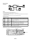
Base Main PCB
Power
Meter
RF
Test Point
BASE Unit
J4
DC IN
9V Jack
1kHz -15dBm
AF GEN.
AC 120V
60Hz
Frequency
Counter
Deviation
Mater
RF
Test Point
J1
TEL Line
Jack
AC
Adapter
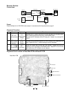
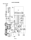
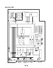
RF Test Point
Base RF PCB
RT3
RT301
S4
J1
TEL LINE Jack
J4
DC IN 9V Jack
S1
PULSE/TONE Switch
TONE
PULSE
S3
CT1
S2
RINGER OFF-ON Switch
ON
OFF