


5
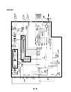
Handset Unit
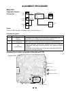
Transmitter Section
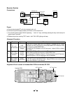
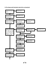
Connection
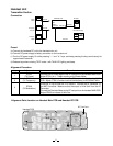
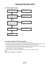
Alignment Point Location on Handset Main PCB and Handset RF PCB
Preset
a) Connect the handseet RF unit to the handset main unit.
b) Connect DC power supply to battery connector on the handset unit.
c) Turn the DC power supply On while pressing " ∗ " and " # " keys, and keep pressing the keys continuously for
approximate 2 seconds.
d) Release keys when entering TEST mode 1 with TALK LED lighting and beep.
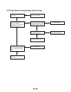
Alignment Procedure
RT501
RF Test Point
step
1
2
3
Adjustment
RT501
(TX Power)
CT601
(TX Frequency)
RT603
(TX Modulation)
Remarks
Connect the RF power Meter to the RF test point on the handset MAIN PCB.
Adjust RT501 for a -7.0dBm reading on the Power Meter.
Connect the Frequency Counter to the RF test point on the handset MAIN
PCB. Adjust CT601 to make sure that the frequency is 903.052467 MHz.
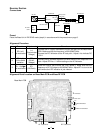
Press the “2” key to enter the TEST Mode 2. Connect the AF Generator to
the MIC Connector. Make sure that the output is 1kHz 9mV from the AF
Generator.
Connect the Deviation Meter to the RF test point on the handset MAIN PCB.
Adjust RT603 to indicate ±8 kHz Dev.
CT601
RT603
J601
RF PCB
Handset PCB
Power
Meter
RF
Test Point
HANDSET Unit
J601
Battery
Connector
1kHz 9mV
AF GEN.
DC 3.8V
Frequency
Counter
Deviation
Mater
RF
Test Point
MIC+Pin
DC Power Supply
MC601