


18
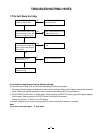
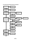
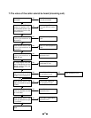
3. The base and handset cannot be connected.
Check whether the base
is able to set in the test
mode 1.
OK
NG
A
Check IC11 and its
peripheral circuit.
Check base RF unit.
NG
Check the TX POWER
and the TX FREQUENCY
on the base unit.
OK
NG
Check base RF unit.
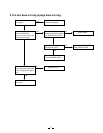
Set the base in the test
mode 3, check whether
deviation of the TX data
is app. 9.0 kHz Dev.
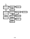
OK
NG Check whether there is a
250 Hz data waveform at
“MOD” of RF unit.
Check RT3, R30, R76,
R77, R91, R49, C122,
C33 and C52.
NG
OK
Check base RF unit.
Set the base in the test
mode 8, 902.952467
MHz (250 Hz ±8 kHz
Dev.) 1mV output signal
from RF test point is
applied. Does the
CHARGE LED light?
OK
NG Check whether there is a
250 Hz data waveform at
RT2 AF test point.
Check IC3, Q1 and their
peripheral circuit.
NG
OK
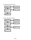
Check whether there is a
250 Hz data waveform at
the Q2 collector.
Check RT2, Q2 and their
peripheral circuit.
NG
OK
Check whether there is a
250 Hz data waveform at
pin 38 of IC11.
Check IC1 and its
peripheral circuit.
NG
OK
Check IC11 and its
peripheral circuit.
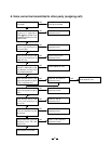
Check whether the
handset is able to set in
the test mode 1.
OK
NG
Check IC604 and its
peripheral circuit.
Check the TX POWER
and the TX FREQUENCY
on the handset unit.
OK
NG
Check handset RF unit.
OK