


22
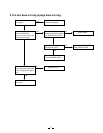
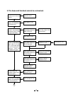
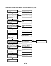
7. The voice of the caller cannot be heard (incoming call).
Can the base and handset be
connected?
See 3. The base and handset
cannot be connected.
OK
NG
The 1 kHz, -15dBm sine
waveform is applied to TEL-
line of the base, can the 1 kHz
sine waveform from the Q3
collector be fed?
Check the base TEL-line
circuit and REPLAY control
circuit.
NG
Check whether there is the
1 kHz sine waveform at
pin 24 of IC1.
Check IC4 and its peripheral
circuit.
NG
OK
OK
Check whether there is the
1 kHz sine waveform at
pin 20 of IC1.
Check IC1 and its peripheral
circuit.
NG
OK
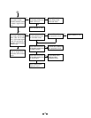
TX output signal from the
base is detected by the liner
detector, can the 1 kHz sine
waveform be fed?
Check base RF unit.
NG
OK
Check whether there is the
1 kHz sine waveform at pin 9
of IC601 on the handset unit.
Check IC601, Q601 and
their peripheral circuit.
NG
OK
Check whether there is the
1 kHz sine waveform at pin 3
of IC603.
Check RT602, Q602 and
their peripheral circuits.
NG
OK
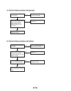
Check whether there is the
1 kHz sine waveform at the
pin 18 of IC603.
Check IC603 and its
peripheral circuit.
NG
OK
Check whether there is the
1 kHz sine waveform at pin
1, 2 of SP801.
Check Q605, Q606 and its
peripheral circuit.
NG
OK
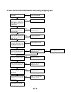
Check SP801 and W801,
W802.
Check handset RF unit.
NG
OK
Check whether there is the
1 kHz sine waveform at
“MOD” RF unit.
Check RT3 and its
peripheral circuit.
NG
OK