


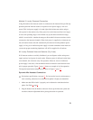
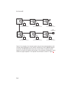

Method 2: Locally Powered Connection
Using this method, the intercom station is connected to the intercom line just like any
phantom-powered intercom station, except that a local power supply is also con-
nected. This local power supply is located right with the intercom station and pro-
vides power for that station only. Since power loss on the intercom lines is no longer
an issue, the operating range is now limited only by the audio transmission range,
which is several miles. Another advantage to this method is that more stations can be
connected to the intercom channels. When local power is supplied to an intercom sta-
tion, the station detects this and automatically disconnects from the phantom power
supply. As long as an Audiocom power supply is located somewhere in the intercom
system, the proper terminating impedance will still be supplied for all stations.
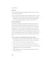
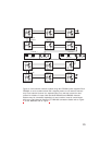
All Locally Powered Intercom Stations (Dry Lines)
If all intercom stations are widely distributed, you can dispense with a main power
supply and use local power for each station. When no power is delivered on the inter-
com channels, this is known as dry-line operation. However, since an Audiocom
power supply is not used, a line termination must be inserted in each intercom chan-
nel for proper operation. Figure 5
, page 14 shows an example of dry line operation.
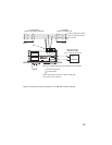
The required termination components are shown in Figure 8, page 16.
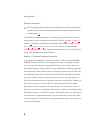
Dynamic-Mic Headset Connection
☞
For headset specifications, see page 18. For best results in noisy environments, a
noise canceling (directional or cardioid) microphone is highly recommended.
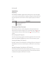
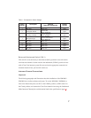
1. Make sure that DIP switch 4 is properly set for balanced or unbalanced micro-
phone. See Table 1, page 7.
2. Plug the headset into the headset connector. Power up the intercom system and
check the sidetone adjustment before placing the station in operation.
9