


General Information
☞
After connecting intercom stations as described below, and before installing the
mounting screws, connect a headset and perform the sidetone adjustment as de-
scribed on page 10.
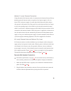
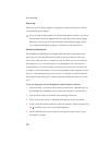
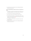
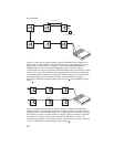
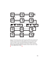
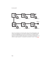
The WM1000 and WM2000 mount in a standard two-gang electrical box. Some ex-
ample intercom system configurations are shown in Figures 2 through 5, pages 12
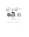
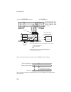
through 14. Detailed connections for the WM1000 and WM2000 are shown in Fig-
ures 6 and 7, pages 15 and 16. There are two basic methods for connecting the
WM1000 and WM2000: 1) using a phantom powered connection, and 2) using local
power. The two methods are discussed below:
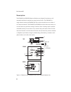
Method 1: Phantom Powered Connection
In this method, operating power and intercom audio are delivered to the WM1000 /
WM2000 over the same wires. The advantage of this setup is simplicity of connec-
tion. Also, the Audiocom power supply automatically provides what is known as a
terminating impedance for the intercom system. Without this terminating impedance,
the sound quality on the channel will be very distorted, and the levels will shift every
time additional stations are connected to the channel. The disadvantage of the phan-
tom power method is that some operating power is lost over very long intercom ca-
bles, and performance will then be reduced at remotely located stations. Generally, if
the intercom stations are located within a few hundred feet of the power supply,
phantom power will be sufficient. The actual distance over which power can be de-
livered can vary, however, depending on the number of stations connected. Increasing
the number of stations will reduce the distance. Note that the range over which power
can be delivered is independent from the range over which audio can be sent. Audio
can be transmitted for several miles, providing that intercom stations are locally pow-
ered as described below.
8
Audiocom®