


16
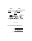
Audiocom®
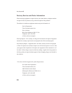
Pair
Pair
Pair
Denotes twisted pair.
Denotes shield.
Channel 1 Audio low / Power
Shield*
DC Common
Shield*
TO POWER
SUPPLY CONNECTOR
TO ADDITIONAL
SINGLE- ORTWO-CHANNEL STATIONS
CableType:22AWG Stranded, 3-PairTwisted-wire, with Shield
Channel 2 Audio low / Power
Channel 2 Audio high / Power
OPTIONAL LOCAL
POWER SOURCE
12 to 15VDC, 65 to 150 mA
+ DC
COMMON
Channel 1 Audio high / Power
*Shield:Earth ground (Connect at power supply only.
Do not short to DC common)
PIN 1
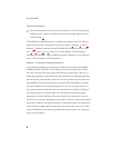
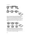
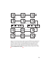
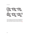
Figure 7. Audiocom mode connections for a WM2000 Intercom Station
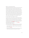
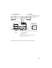
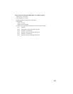
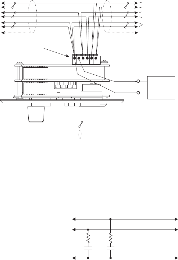
Resistors 300 Ohm, 1/4W
Capacitors 22 f, 35V
Non-polarized Electrolytic
µ
Channel audio low
Channel audio high
Common
Figure 8. Audiocom mode line termination for dry-line operation. (One required for
each channel.)