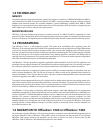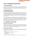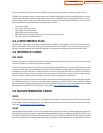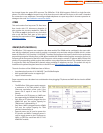
SAMPLE CONFIGURATION
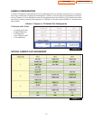
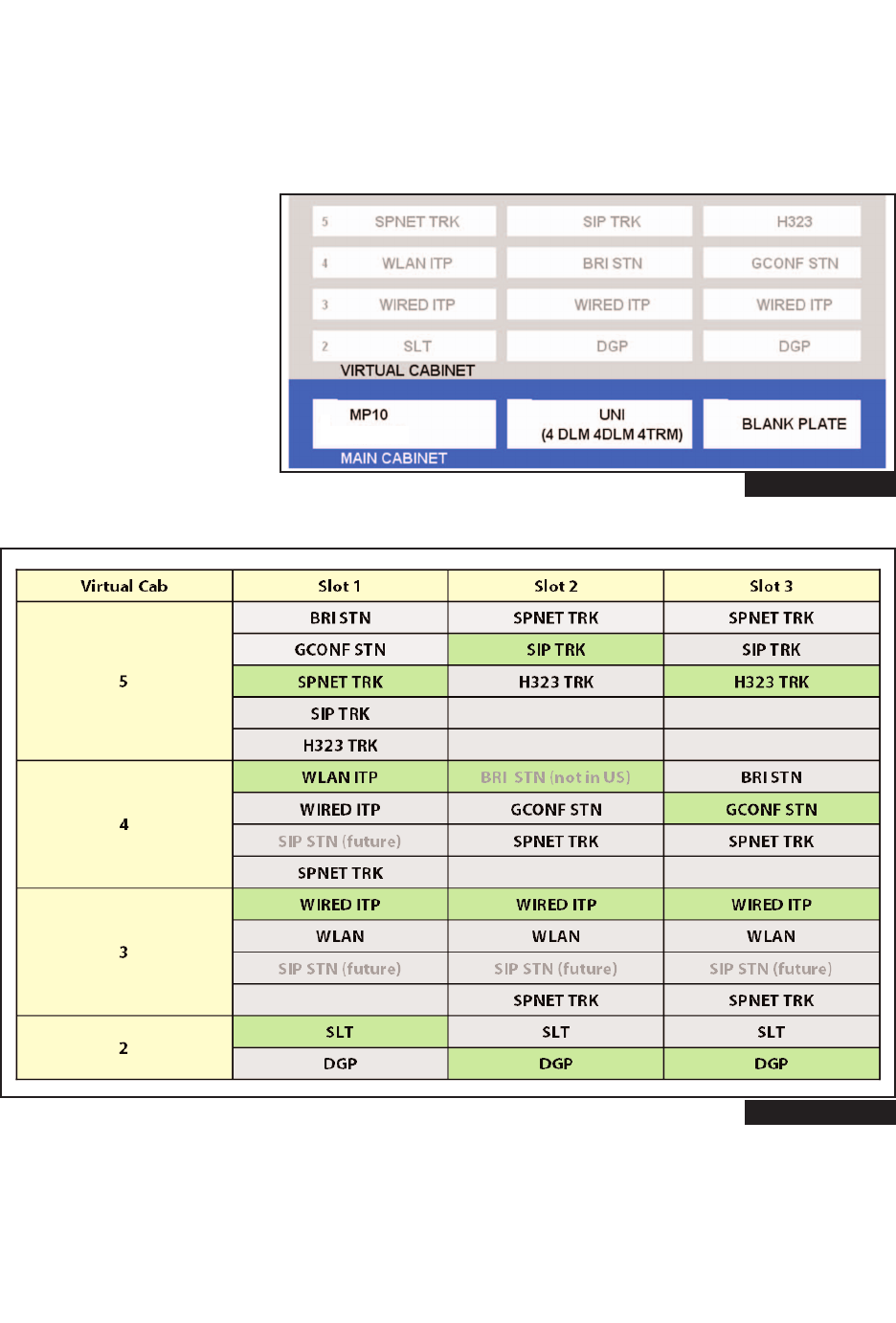
To better understand how the OfficeServ 7100 is configured,below is an example of a practical 4 x 12 configura-
tion using a combination of digital and ITP telephones. Cabinet 1 shows the type of card installed in each phys-
ical slot. Cabinets 2~5 show the default to the virtual assignments for each virtual slot. The IP telephones may be
connected to existing (external) data equipment or OfficeServ 7100 data module (4SWM) in a separate stand
alone cabinet.
Cabinet 1: Sample 4 x 12 Default Slot Configuration
VIRTUAL CABINET SLOT ASSIGNMENT
12 Stations and 4 Trunks
• 4 Analog Loop Trunks
• 8 Digital Telephones
• 4 IP Telephones
• 4 MGI Channels (VoIP)
• 4 Voice Mail Ports
FIGURE 1-6
1.5
(MGI-4)
(VM-4)
FIGURE 1-7
Home Page
Table of Contents


