


SSA-424 USER MANUAL 7
2 Installation
2.1 UNPACKING AND INSPECTING
Immediately upon receipt of the equipment, carefully
inspect the shipping container and the contents for
any discrepancies or damage. Should there be any,
notify the freight company and the dealer at once.
The following items are included:
Qty Description
1 SSA-424 Dual Digital Hybrid
1 Power Pack with cord,100-250 VAC, 50/60Hz
1 Warranty Card
1 User Instruction Manual
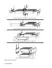
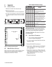
2.2 MOUNTING
Place the SSA-424 on a desktop, or install it in an
equipment rack using an RTS MCP Rack Mount Kit.
Several rack mount options are available (Figure2,
page 8). There are no special ventilation require-
ments for the SSA-424, but allow for ventilation
around the power pack.
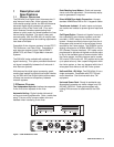
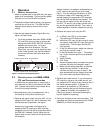
✏ If the SSA-424 has the call signal option, the
power indicator flashes whenever a call
signal is received from either 2-wire line, and
activity on the level display helps to indicate
which line is calling. If the SSA-424 is
positioned near the 4-wire operator, this can
be used as an incoming call indication for the
4-wire system, if desired (although other
methods are available as described in
paragraph 2.5).
✏ You may wish to read about the internal
mode DIP switches before mounting the
SSA-424. For further information, see Mode
Switch Settings, page 16.
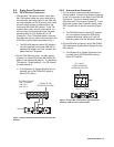
2.3 4-WIRE AUDIO CONNECTIONS
2.3.1 ADAM, ADAM CS, OR ZEUS AUDIO
CONNECTION
1 Use standard 9-pin or RJ11 keypanel cables.
Connect from one port of your intercom system
to J2A or J3A (System A connection) on the
back of the SSA-424. Connect from another
port to J2B or J3B (System B connection).
2 On the SSA-424 front panel, set the 4W
LEVEL REF SEL switches to the +8dB posi-
tion.
2.3.2 AUDIO CONNECTIONS FOR OTHER 4-WIRE
COMMUNICATIONS SYSTEMS
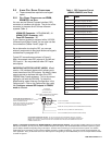
1 Construct 9-pin or RJ11 cables to connect from
you 4-wire system to the SSA-424. To connect to
the System A hybrid, use either J2A or J3A; for
the System B hybrid, use either J2Bor J3B. Pin
connections are as follows:
9-Pin Connection
Connector Type (on SSA-424 end of cable): 9-pin
male D-subminiture
Pin 1: No connection
Pin 2: No connection
Pin 3: No connection
Pin 4: Balanced Audio + output (to 4-wire
system)
Pin 5: Balanced Audio - output (to 4-wire
system)
Pin 6: No connection
Pin 7: Balanced Audio - input (from 4-wire
system)
Pin 8: Balanced Audio + input (from 4-wire
system)
Pin 9: No connection
RJ11 Connection
Connector Type (on SSA-424 end of cable):
RJ11 plug
Pin 1: No connection
Pin 2: Balanced Audio + input (from 4-wire
system)
Pin 3: Balanced Audio + output (to 4-wire
system)
Pin 4: Balanced Audio - output (to 4-wire
system)
Pin 5: Balanced Audio - input (from 4-wire
system)
Pin 6: No connection
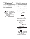
2 On the SSA-424 front panel, set the 4W LEVEL
REF SEL switches to the position which most
closely matches the audio input and output levels
of your 4-wire system. If you don’t know the
levels, select +4dB for now.