


SSA-424 USER MANUAL 17
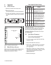
6 Set the 2W CHAN SEL switches to either OFF
position.
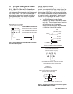
7 Input a 1kHz, -10dBu test signal at the 4-wire
audio input. Use either connector:
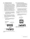
9-Pin Connector
Pin 7:Balanced Audio - input
Pin 8:Balanced Audio + input
RJ11 Connector
Pin 2:Balanced Audio + input
Pin 3:Balanced Audio - input
8 Adjust RV102 (System A) or RV202 (System B)
while watching the bottom display (TO2W). All of
the green displays should be lit and no amber
displays should be lit.
9 Remove the test signal. This completes the
adjustment.
4.4 CALL SIGNAL OPTION CARD INSTALLATION
Use these instructions to install a Call Signal Option
Card in an SSA-424 that was originally ordered
without it.
1 Disassemble the SSA-424 as previously de-
scribed.
2 Assemble the standoffs to the circuit board using
the supplied screws and lockwashers.
3 Connect the supplied power cable from J8 on the
option card to J303 on the main board of the
SSA-424.
4 Insert the connectors on the option card into the
connectors on the main board.
5 Use the remaining screws and lockwashers to
secure the standoffs to the main board.
6 Reassemble the SSA-424.
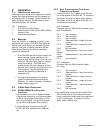
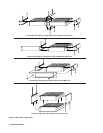
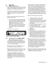
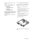
Figure 11. The Call Signal Option Card after installation in the
SSA-424.