


6 SSA-424 USER MANUAL
1.3 FRONT AND BACK PANEL DESCRIPTIONS
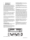
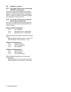
1.3.1 FRONT PANEL
There is a power ON/OFF and call indicator at the left
of the front panel. This indicator lights continuously
when the SSA-424 is turned on and flashes when an
incoming call signal is detected. The remainder of
the front panel is divided into controls and indicators
for the two separate hybrids, labeled SYSTEM A and
SYSTEM B. For each hybrid, there is a 10-segment,
peak reading level meter to display the 4-wire output
level (TO 4W). There is a recessed level set control
to the left of the 4-wire meter (LEVEL SET) and there
is also a recessed, 5-position range select control for
the 4-wire output (4W LEVEL REF SEL). Under the
4-wire meter, is an identical meter for the 2-wire
output level, and there is a recessed level set control
for the 2-wire output to the left of the meter. Under
the 2-wire meter, there is a recessed, 5-position
selector. The selector has two OFF positions for
when no 2-wire input is connected. The three
remaining switch positions select the 2-wire system
as follows: position 1 selects RTS TW channel 1;
position 2 selects RTS TW channel 2 or a Clear-Com
channel; the BAL position selects an Audiocom
balanced channel. There are 3 LED indicators to
display the current selection (2W CHAN SEL).
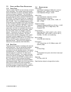
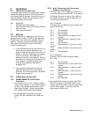
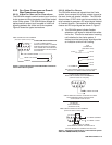
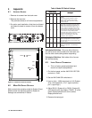
1.3.2 BACK PANEL
The power pack connector is located at the right end
of the back panel. This is a locking DIN connector.
The remainder of the back panel is divided into
connectors for the two separate hybrids. Connectors
are labeled with “J” numbers followed fy “A” or “B” to
indicate system A or system B. For each hybrid,
there is an AUX connector. This is used to connect
to/from the optional call signal card. Below the AUX
connector, there are both a DB9F connector and an
RJ11 connector for 4-wire intercom connection.
These are directly compatible with standard ADAM/
Zeus keypanel cables. Next to the 4-wire connectors,
there is a 3-pin female XLR audio connectorfor
connection to the 2-wire intercom system. The pin-
out of this connector is determined by the position of
the TW CHAN SEL control on the front panel.
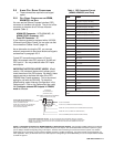
1.4 SPECIFICATIONS
2-Wire Ports
Input/Output Impedance: 5,000 ohms, nominal
Operating Level: -10dBu to 0 dBu, nominal
Level Adjustment Range: ±12dB
4-Wire Ports
Input Impendance: 10k ohms, nominal
Output Impedance: 200 ohms
Operating Levels: -10 dBu, 0 dBu, +4 dBu, +8
dBu, +12 dBu
System to System
Frequency Response:200 Hz to 4.5 kHz, +1/-6dB
S/N Ratio (Ref 1 kHz, 0 dB@2-wire): TBD
Crosstalk: TBD
Environmental
Operating Temp: -20°C to 50°C (-4°F to 122°F)
Storage Temp: -40°C to 85°C (-40°F to 185°F)
Humidity: 0 to 95%, non-condensing
Mains Voltage
100 to 250 VAC, 50/60 Hz
Dimensions
1.72” (44mm) high x 8.19” (208mm) wide x 8.0”
(204mm) deep
Weight
5.0 lbs (2.3kg)
Finish
Thermoplastic front panel, almunimum case, light
gray finish
Approvals
UL, CSA, UDE, CE
Specifications subject to change without notice.