


16 SSA-424 USER MANUAL
4 Appendix
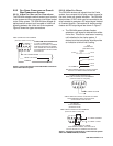
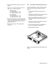
4.1 INTERNAL ACCESS
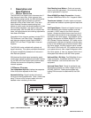
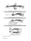
1 Remove six screws from the back cover.
2 Remove the top cover.
This provides access to all internal adjustments.
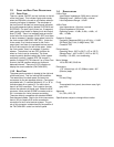
3 For option card installation, slide the circuit board
out toward the back to remove it from the bottom
cover.
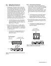
AUX
J4B
J3B
J2B
J1B
J1A
J2A
J3A
J4A
AUX
4 WIRE SYSTEM 4 WIRE SYSTEM
2 WIRE SYSTEM
Telex Communications, Inc., Made in U.S.A.
RTN
+5V
RTN
+15V -15V
-15V 0.3A
+15V 1.6A
+5V 3A
J5 POWER
Figure 9. Location of screws for disassembly.
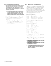
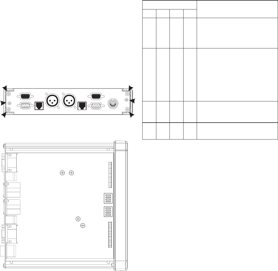
RV102
RV101
RV202
RV201
S301
S302
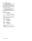
Figure 10. Locations of internal controls.
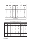
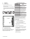
4.2 MODE DIP SWITCH SETTINGS
S301 controls the operating mode for System B and
S302 controls the operating mode for System A.
Settings are summarized in Table 4
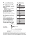
Table 4. Mode DIP Switch Settings
sgnitteShctiwSsgnitteShctiwS
sgnitteShctiwS
sgnitteShctiwSsgnitteShctiwS
noitpircseDnoitpircseD
noitpircseD
noitpircseDnoitpircseD
11
1
1122
2
2233
3
3344
4
44
ffOffOffOffO
edoMxelpuDlluF/flaH,1noitarugifnoC
:)tluafed(
.sedomneewtebsehctiwsyllacitamotuA
hgihsierehterehwsnoitautisnilufesU
sierehtnehwlufesuoslA.esiontneibma
.kcabdeefcitsuoca
nOffOffOffO
:edoMxelpuDlluFdehctiwS,2noitarugifnoC
9-3xelpudllufotxelpudflahmorfsehctiwS
-4ehtnosnigebnoitasrevnocretfasdnoces
-06litnuedomxelpudllufnisyatS.enileriw
sihT.sesaecnoitasrevnocretfasdnoces09
fosdoidrepgnirudteiuqenilehtpeekotspleh
larutangnittimrepelihw,noitasrevnocon
sisihT.gniklateraelpoepnehwnoitasrevnoc
ynamrofedomgnitarepoderreferpeht
-esolc,tsafrofylralucitrapdna,snoitautis
.snoitarepomaet,noitanidrooc
nOffOffOnO
:edoMxelpuDlluFdekcoL,3noitarugifnoC
dirbyhaecnotub,2noitarugifnocsaemaS
edomtahtnisyatsti,edomxelpud-llufsretne
.nwod-rewoplitnu
ffOffOnOffO
:edoMxelpuDlluF/flaH,4noitarugifnoC
rehgihhtiwtub,1noitarugifnocotralimiS
.ytivitisnes
Half-duplex Definition: Only one side of the line
can talk at a time and the other side must wait until
the first side is done talking before responding.
Full-duplex Definition: Both sides of the line can
talk simultaneously.
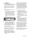
4.3 LEVEL DISPLAY CALIBRATION
✏ This is a factory preset adjustment and
should not require readjustment.
1 On the front panel, set the 4W LEVEL REF SEL
controls to -10dB.
2 Set the 2W CHAN SEL switches to 1.
3 Input a 1kHz, -10dBu test signal at J1A (System
A) or J1B (System B). (Pin 1, signal common;
pin 2, signal high.)
4 Adjust RV101 (System A) or RV201 (System B)
while watching the top display (TO4W). All of the
green displays should be lit and no amber
displays should be lit.
5 Remove the test signal.