


SSA-424 USER MANUAL 11
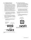
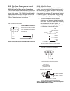
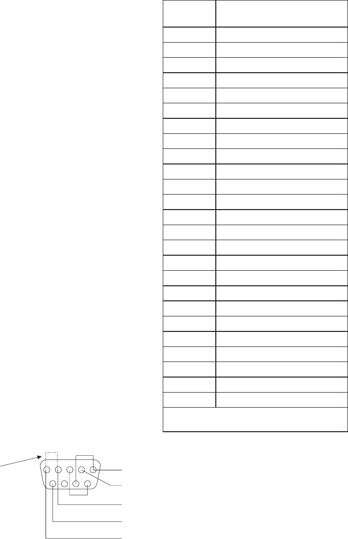
DB9F CABLE
(View from solder or crimp side)
CONNECTOR PIN NUMBERS
15432
67 89
TO SSA-424
AUX CONNECTOR
(SYSTEM A OR B)
FROM GPI OUT #1 (4-WIRE CALL SEND OUTPUT)
UIO-256 APPLICATION NOTE: GPI OUT - ATTHE UIO-256 END, USETHE NORMAL OPEN (NO) CONTACT
FOR GPI OUT CONNECTION, AND USETHE RELAY COMMON CONTACT FORTHE COMMON CONNECTION.
- USETHE INPUT HIGH PIN FORTHE GPI IN CONNECTION, AND USETHE COMMON PIN FOR THE
COMMON CONNECTION.
GPI IN
CLEAR-COM APPLICATION NOTE: IF A
CALL ENABLE/INHIBIT SWITCH IS NOT
USED, A JUMPER MUST BE
INSTALLEDTO ENABLE CALL SIGNALING.
THE JUMPER IS NOT REQUIRED FOR
ANY OTHER APPLICATION.
FROM GPI OUT #2 (OPTIONAL CALL ENABLE/INHIBIT CONTROL)
GPI OUT COMMON (SEE UIO-256 APPLICATION NOTE)
TO GPI IN #1 (4-WIRE CALL RECEIVE INPUT)
TO GPI IN COMMON
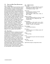
2.5 4-WIRE CALL SIGNAL CONNECTIONS
✏ These connections require the call signal
option.
2.5.1 CALL SIGNAL CONNECTIONS FOR ADAM,
ADAM CS, AND ZEUS
You can use the General Purpose Interface (GPI)
connector to interface call signals. The pin-out of the
connector is the same for all of these intercom
systems (Table 1).
ADAM GPI Connector: XCP-ADAM-MC, J11
ADAM CS GPI Connector: J903
Zeus GPI Connector: J27
If your intercom system is equipped with a UIO-256
Universal Input/Output Frame, you can also use that
for connections (Tables 2 and 3, page 12).
As an alternative to using the GPI, you can use
external components to send and receive call signals
as described in paragraph 2.5.2.
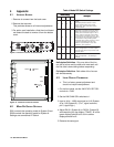
Typical GPI connections are shown in Figure 5.
Note, the example uses GPI outputs #1 and #2 and
GPI input #1. You may substitute other GPI inputs
and outputs.
IMPORTANT NOTE FOR AZEDIT USERS: AZedit
version 1.06 includes a feature which allows you to
invert the action of the GPI outputs. By default, these
outputs are set to duplicate the actio of the RTS
FR9528 Relay Frame accessory. This is the correct
setting for use with the SSA-424. To check the
AZedit setting, select Intercom Configuration in the
Options menu. Click on the Options tab, then verify
that Configure onboard GPI outputs in FR9528
mode is selected.
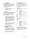
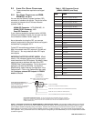
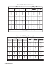
Table 1. GPI Connector Pin-out
(ADAM, ADAM CS, and Zeus)
.oNniP.oNniP
.oNniP
.oNniP.oNniPnoitcnuFnoitcnuF
noitcnuF
noitcnuFnoitcnuF
1)CDV81-5(hgiH1#tupnIIPG
2)CDV81-5(hgiH2#tupnIIPG
3)CDV81-5(hgiH3#tupnIIPG
4)CDV81-5(hgiH4#tupnIIPG
5)CDV81-5(hgiH5#tupnIIPG
6)CDV81-5(hgiH6#tupnIIPG
7)CDV81-5(hgiH7#tupnIIPG
8)CDV81-5(hgiH8#tupnIIPG
9*nommoC
01*nommoC
11*nommoC
21*nommoC
31*nommoC
411#tuOIPG
512#tuOIPG
613#tuOIPG
714#tuOIPG
815#tuOIPG
916#tuOIPG
027#tuOIPG
128#tuOIPG
22*nommoC
32*nommoC
42*nommoC
52*nommoC
rotupniIPGynahtiwnipnommocelbaliavaynaesU*
.tuptuo
Figure 5. Call signal connections for ADAM, ADAM CS, or Zeus Intercom Systems. This example usesGPI outputs #1 and #2 and
GPI input #1; however, you may use any other available GPI inputs and outputs. The Call Enable/Inhibit connection is optional. It gives
you the ability to disable call signaling using a GPI output. However, when connecting to a Clear-Com intercom system, if an enable/
inhibit switch is not connected, a jumper must be installed as shown to enable call signaling. The jumper should not be installed for any
other application. Note, you DO NOT have to use GPI outputs for call signaling or call enable/inhibit: you can use simple switches instead
as shown in Figure 6.