


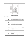

Physical Details
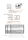
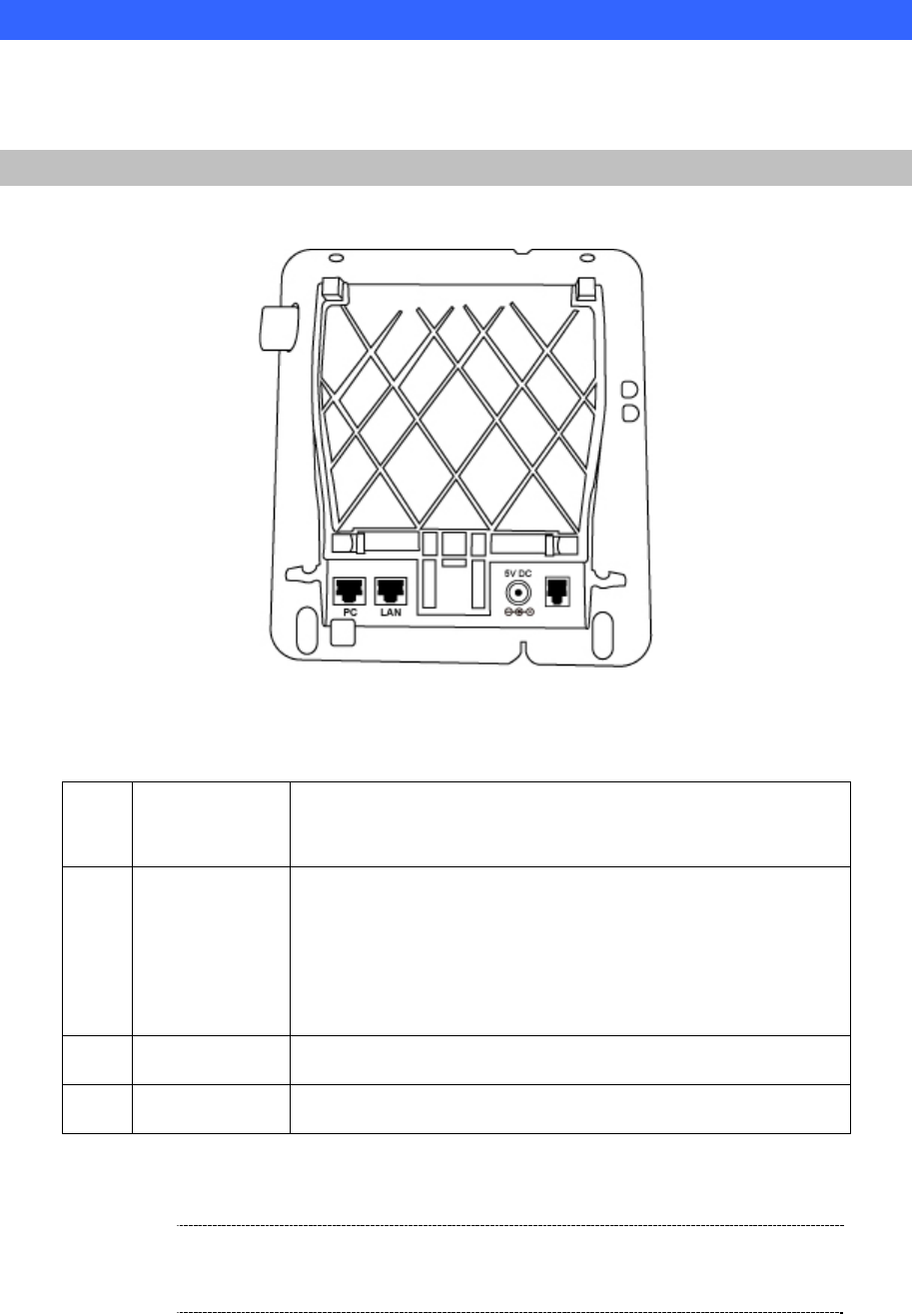
The following figure illustrates the front/rear panel of IP Phone.
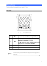
Rear View
Rear Panel of VIP-254T/VIP-254PT
1 PC
RJ-45 connector, to maintain the existing network structure,
connected directly to the PC through straight CAT-5 cable
2 LAN
RJ-45 connector, for Internet access, connected directly to
Switch/Hub through straight CAT-5 cable.
The LAN interface also can be connected with 802.3af PoE
switch or converter for power supply (VIP-254PT)
3 DC 5V
5V DC Power input outlet
4. Handset
RJ-11 connector, connected directly to the Handset.
For VIP-254PT, either PoE or AC adapter can be deployed at
LNote
one time
8