


A. Connector Pin Assignments
A-2 June 2004 8900-A2-GB20-30
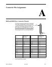
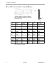
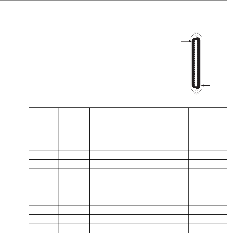
Model 8968 Line Card Telco Connector Pinouts
The Telco 50-pin connectors on the faceplate of
the Model 8968 line card provide the 2-wire loop
interface from each DSL port to either the POTS
splitter shelf or, if the loop is not being shared with
POTS, then to the Main Distribution Frame (MDF).
The following table lists the pin assignments for
each of these interfaces.
The bottom connector (Connector 1) services
ports 1–24 and the top connector (Connector 2)
services ports 25–48
Pins 25 and 50 are not used.
00-16714
Pin
Number 50
Pin
Number 1
Connector 1
Port
Connector 2
Port
Connector Pins
(Tip, Ring)
Connector 1
Port
Connector 2
Port
Connector Pins
(Tip, Ring)
Port 1 Port 25 1, 26 Port 13 Port 37 13, 38
Port 2 Port 26 2, 27 Port 14 Port 38 14, 39
Port 3 Port 27 3, 28 Port 15 Port 39 15, 40
Port 4 Port 28 4, 29 Port 16 Port 40 16, 41
Port 5 Port 29 5, 30 Port 17 Port 41 17, 42
Port 6 Port 30 6, 31 Port 18 Port 42 18, 43
Port 7 Port 31 7, 32 Port 19 Port 43 19, 44
Port 8 Port 32 8, 33 Port 20 Port 44 20, 45
Port 9 Port 33 9, 34 Port 21 Port 45 21, 46
Port 10 Port 34 10, 35 Port 22 Port 46 22, 47
Port 11 Port 35 11, 36 Port 23 Port 47 23, 48
Port 12 Port 36 12, 37 Port 24 Port 48 24, 49