


8900-A2-GB20-30 June 2004 A-1
A
Connector Pin Assignments
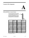
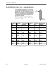
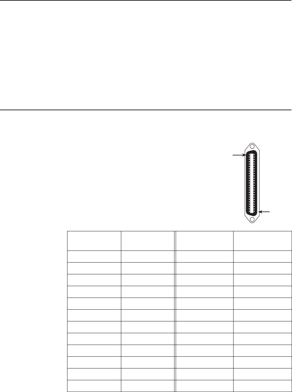
8620 and 8820 Telco Connector Pinouts
For 24-port line cards, the Telco 50-pin connectors
on the back of the 8620 BAC chassis (numbered
1–3) and the 8820 BAC chassis (numbered 1–18)
provide the 2-wire loop interface from each DSL
port to either the POTS splitter shelf or, if the loop
is not being shared with POTS, then to the Main
Distribution Frame (MDF). The following table lists
the pin assignments for each of these interfaces.
Pins 25 and 50 are not used.
Port
Connector Pins
(Tip, Ring) Port
Connector Pins
(Tip, Ring)
Port 1 1, 26 Port 13 13, 38
Port 2 2, 27 Port 14 14, 39
Port 3 3, 28 Port 15 15, 40
Port 4 4, 29 Port 16 16, 41
Port 5 5, 30 Port 17 17, 42
Port 6 6, 31 Port 18 18, 43
Port 7 7, 32 Port 19 19, 44
Port 8 8, 33 Port 20 20, 45
Port 9 9, 34 Port 21 21, 46
Port 10 10, 35 Port 22 22, 47
Port 11 11, 36 Port 23 23, 48
Port 12 12, 37 Port 24 24, 49
00-16714
Pin
Number 50
Pin
Number 1