


GDK-20W DIGITAL WIRELESS KEY TELEPHONE SYSTEM
30
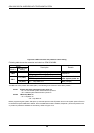
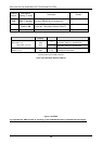
Jumper/
Switch
Manufacture
Setting (T mode)
Description Remark
SW1 &
CN2
SW1 :OFF
CN2 : T position
S0 or T0 interface mode selection for the
port and PEB2086 device respectively.
SW2
Pin1-2: OFF
Pin3-4 : ON
#1 and #2 : External Power feeding ON/OFF.
#3 and #4 : Termination Resistor ON/OFF
SW3 ON
Termination Resistor ON/OFF Only for T0 interface.
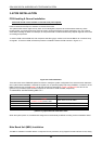
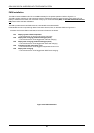
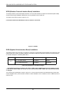
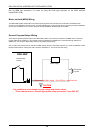
(a) Selection Method
Port Connector
& Switch
Mode Selection Method
So/To (CO1-2 or
T
Move short pins to CN2’s ‘T’ position
Move SW1, SW2 to ‘T’ position(OFF)
2So station 130-131)
SW1
SW2
CN2
S
Move short pins to CN2’s ‘S’ position
Move SW1, SW2 to ‘S’ position(ON)
To
(CO3-4 or 1-2)
SW3
T only
Move SW3 to ON position
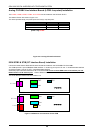
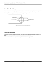
(b) Port meaning for STIB2 of SLOT2
[Table 3.4.3] S/T Mode Selection Method
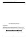
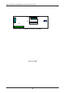
Figure 3.4.9 STIB2
It is noted that the ‘PWR’ and the ‘R’’ markings on the STIB2 & STIB card are switched with above figure.