


GDK-20W DIGITAL WIRELESS KEY TELEPHONE SYSTEM
26
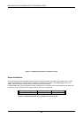
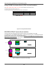
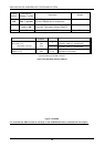
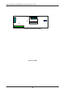
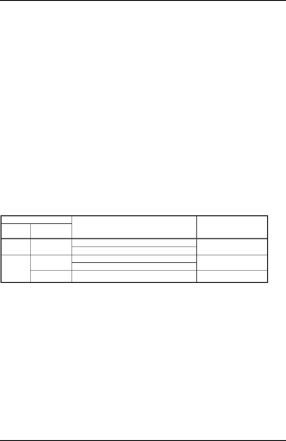
Figure 3.4.3 RGU connector and protection switch setting
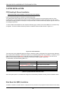
Following table shows the connector and switch on GDK-20W MBU.
Switch
ISSUE 1
Manufacturer
setting
Description Remark
Pin 1&2 short: 50Hz ring signal(sine wave)
CN23
RGU plugged: 25Hz ring signal(square wave)
Dependent on country
adaptation.
ON: For database protection.
1-1 ( OFF)
OFF: For system default.
Turn ON the switch
after system power on.
SW 1
1-2 (OFF)
OFF : Loop back OFF OFF (Always)
The MBU has a two position DIP switch(SW1). The following is the function of each switch position :
Knob 1 System data base initialization when power on
-. On : Do not initialize system data base when power on.
-. Off : Initialize system data base when power on.
Knob 2 ISDN Loop Back on
-. On : Loop Back on
-. Off : Loop Back off
Before programming the system, SW1(knob 1) should be placed in the Off position and turn the system power off and on
to initialize the system database to default. Once the database has been initialized, SW(knob 1) should be placed in the
on position to protect the database in the memory. Refer to Figure 3.4.3.