


CONTENTS
TM-D710A/E III
9.5.3.7 Transceiver Menu > Variable Level
of Data Terminal.......................... 75
9.5.3.8 Transceiver Menu > SQC Output
Logic ............................................ 75
9.5.4 Unique Functions............................76
9.5.4.1 Importing TravelPlus for Repeaters
Files ............................................. 76
9.5.4.2 Importing .hmk Files.................... 76
9.5.4.3 Exporting .hmk Files.................... 76
9.5.4.4 Exporting .html Files.................... 76
9.5.4.5 Splash Window............................ 76
9.5.5 Useful Functions.............................77
9.5.5.1 Verifying Firmware Versions ....... 77
9.5.5.2 Increasing Size of Characters ..... 77
9.5.5.3 Configuring the Names for PM or
Memory Groups........................... 77
9.5.5.4 Configuring User Names with
MCP-2A....................................... 77
9.5.5.5 Configuring How Memory Channels
Display......................................... 77
9.5.5.6 Memory Channel Shortcut .......... 78
9.5.5.7 COM Port Shortcut...................... 78
10 HOW TO UPDATE FIRMWARE....79
10.1 Firmware ....................................... 79
10.2 Verifying Necessary Equipment .... 79
10.3 How to Verify Firmware Version.... 80
10.3.1 Checking the Transceiver Operation
Panel ..............................................80
10.3.2 Checking with MCP-2A...................80
10.3.3 Firmware Update for SmartBeaconing
and Other Enhancements...............81
10.4 How to Get Newest Firmware/
Software ........................................ 81
10.5 How to Update............................... 81
11 MISCELLANEOUS TOPICS.........82
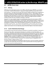
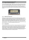
11.1 RC-D710 (Operation Panel /
APRS-ready Standalone TNC)...... 82
11.1.1 Models Supported for use with
RC-D710.........................................82
11.1.1.1 Connection Example 1: Connecting
RC-D710 to TM-V7A/E.............. 82
11.1.1.2 Connection Example 2: Connecting
RC-D710 to TM-D700A/E,
TM-V708A ................................. 83
11.1.1.3 DATA Terminal Pins (PG-5J).... 83
11.2 Adjusting Input and Output
Levels............................................ 84
11.2.1 How to Configure Input/Output
Levels of RC-D710.........................84
11.3 Schematic Diagram of the Optional
PG-5J Interface Kit........................ 85
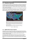
11.4 AvMap (written by Don Arnold,
W6GPS) ........................................ 85
12 APPENDIX ................................... 88