


6 APRS IN ACTION
TM-D710A/E CONTENTS 21
6.1.4 Simultaneously using Decay Algorithm and Proportional Pathing
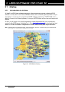
Refer to the diagram below to understand what occurs when both Decay Algorithm and
Proportional Pathing are used at the same time.
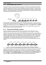
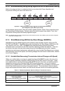
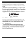
Figure 6-3 Switching between Decay Algorithm and Proportional Pathing
(when Stopped=1 (knot); Moving=3 (knots))
As the example above shows, when the mobile’s speed exceeds 3 knots, Decay Algorithm stops
and Proportional Pathing begins. Similarly, when the mobile’s speed drops below 1 knot, then
Proportional Pathing stops and Decay Algorithm begins.
Note: The Stopped value cannot be configured higher than the Moving value, and the Moving value cannot be configured
lower than the Stopped value.
6.1.5 SmartBeaconing (Written by Steve Bragg, KA9MVA)
SmartBeaconing was added beginning with operation panel firmware version 2.00 for the TM-
D710A/E and RC-D710. SmartBeaconing was developed by Mr. Steve Bragg, KA9MVA and Mr.
Tony Arnerich, KD7TA in 1998. SmartBeaconing uses the traveling direction and speed
information that is received from the GPS receiver to efficiently transmit the beacon. There are
two factors that come into play when determining how SmartBeaconing functions: distance
traveled since last beacon transmission, addressed by using Variable Rate Beaconing to change
the transmission interval with speed, and heading change since last beacon transmission, referred
to as Corner Pegging.
6.1.5.1 Variable Rate Beaconing (Transmission Interval Changes with Speed)
When your mobile station is moving at a speed less than LOW SPEED as set in the menu, the
position beacon repeatedly transmits at the interval of SLOW RATE as set in the menu. When
your mobile station is moving faster than HIGH SPEED as set in the menu, the position beacon
repeatedly transmits at the interval of FAST RATE as set in the menu. And if your mobile is
traveling at any speed between LOW SPEED and HIGH SPEED, then the beacon transmits at an
interval that varies linearly according to the speed traveled. The transmission interval extends
longer as the speed becomes slower, and the interval becomes shorter as the speed gets faster.
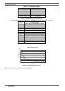
Table 6-1 Relationship between Speed and Beacon Transmission Interval
Speed Transmission Interval
Over HIGH SPEED FAST RATE
Under HIGH SPEED
Over LOW SPEED
(Only when HIGH SPEED ≥ LOW SPEED )
Calculate using the formula below:
FAST RATE x HIGH SPEED ÷ current speed = transmission
interval time
Under LOW SPEED SLOW RATE
Now
Proportional
Pathing
Returns
to Decay
Algorithm
Velocity (Knots)
Status
02 213335
Decay Decay DecayProportional Proportional Proportional Proportional