


67
1
2
3
4
5
6
7
8
9
10
11
12
13
14
15
16
17
18
19
20
21
22
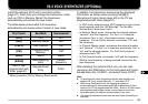
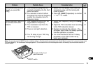
INSTALLING OPTIONS
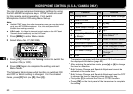
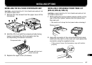
INSTALLING THE VS-3 VOICE SYNTHESIZER UNIT
CAUTION:
ALWAYS SWITCH OFF THE POWER AND UNPLUG THE
DC POWER CABLE FIRST.
1 Remove the five screws from the upper cover of the
transceiver.
2 Hold the VS-3 unit with the component side facing
inward, and insert the VS-3 connector into the
corresponding transceiver connector.
3 Replace the upper cover (5 screws).
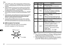
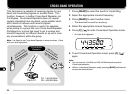
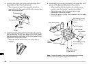
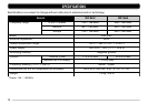
INSTALLING A DETACHABLE FRONT PANEL KIT
(DFK-3C/ DFK-4C/ DFK-7C)
CAUTION:
ALWAYS SWITCH OFF THE POWER AND UNPLUG THE
DC POWER CABLE FIRST.
1 While sliding the spring-loaded release switch on the
rear of the front panel, remove the front panel from
the main unit.
• Be careful not to drop the front panel when releasing it.
2 Hang the connector of the connectorized front panel
cable onto the catch on the main unit, and secure the
connector using the supplied screw.
• If the screw is loose, the transceiver may not function
properly.
Release switch
Viewed with the front
panel removed
K
E
N
W
O
O
D
F
M
D
U
A
L
B
A
N
D
E
R
T
M
-G
7
0
7
K
E
N
W
O
O
D
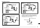
FM DUAL BANDER TM-G707
KENWOOD
FM DUAL BANDER TM-V7
Component side