


ADDENDUM TO ISSUE 4 OF THE AXXESS MANUALOCTOBER 1997
Page 36 of 73
RS-232-C Changes and Corrections
The CPU/MEM, CPU020/PCM, and Options Card
RS-232-C connection information described on pages
2–35 and 2–36 in the Issue 4 manual should be modi-
fied as follows:
If necessary, an eight-wire MOD-TAP modular adapter
and an eight-wire reversing (inverting) line cord can be
used for special applications requiring hardware flow
control. The pin functions of the AXXESS CPU/MEM
Card, CPU020/PCM Card, and Options Card RS-232-C
ports are listed in the following chart.
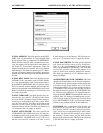
NOTE: The PC or output device RS-232-C ports must
be configured as Data Terminal Equipment (DTE). The
AXXESS RS-232-C ports are always configured as
Data Carrier Equipment (DCE).
AXX. DB9 DB25
SIGNAL NAME
FUNCTION PIN PIN PIN
No Connection 1
No Connection 2
Signal Ground Reference Ground 3 5 7
Transmit Data (TXD) Data to Axxess 4 3 2
Data Term. Ready (DTR)* Signal to Axxess* 5 7 4
Receive Data (RXD) Data from Axxess 6 2 3
Data Set Ready (DSR) Signal from Axxess 7 6 6
(always true)
Clear To Send (CTS) Signal from Axxess 8 8 5
*TheCPUCardRS--232--C port does not support DTR. All other
RS--232--C ports (MEM and CPU020/PCM) do support DTR.
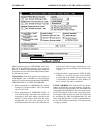
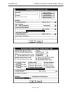
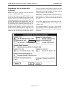
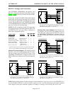
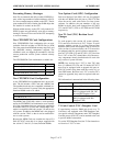
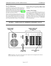
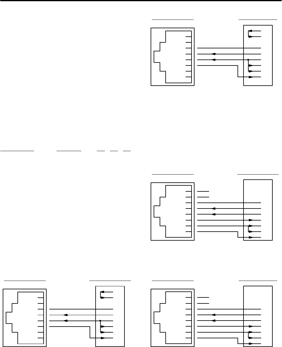
Software flow control adapters: The following wiring
diagrams can be used to build adapters that will, with a
line cord, connect one of the RS-232-C ports on the
CPU/MEM, CPU020/PCM, or Options Card(s) to the
DB9 or DB25 ports found on most PCs and output de-
vices.
AXXESS RS-232-C PC/OUTPUT DB25
7
2
6
3
8
20
1
2
3
4
5
6
7
8
(inside jack)
GND
TXD
DTR*
RXD
RTS
CTS
4
5
GND
TXD
DTR
RXD
DSR
DCD
*TheCPUCardRS--232--C port does not support DTR. All
other RS--232--C ports (MEM and CPU020/PCM) do support
DTR. DB25 internal jumpers: 4–5 and 20–6–8.
AXXESS RS-232-C PC/OUTPUT DB9
5
3
6
2
1
4
1
2
3
4
5
6
7
8
(inside jack)
GND
TXD
DTR*
RXD
RTS
CTS
7
8
GND
TXD
DTR
RXD
DSR
DCD
*TheCPUCardRS--232--C port does not support DTR. All
other RS--232--C ports (MEM and CPU020/PCM) do support
DTR. DB9 internal jumpers: 7–8 and 4–6–1.
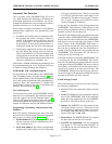
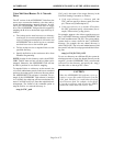
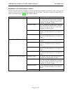
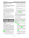
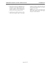
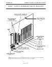
Hardware flow control adapters: The following wir-
ing diagrams can be used to build adapters that will,
with a line cord, connect one of the RS-232-C ports on
the CPU/MEM, CPU020/PCM, or Options Card(s) to
the DB9 or DB25 ports found on most PCs and output
devices.
DSR
AXXESS
RS-232-C PC/OUTPUT DB25
7
2
3
8
6
4
1
2
3
4
5
6
7
8
(inside jack)
GND
TXD
DTR*
RXD
GND
TXD
RTS
DCD
RXD
DSR
*TheCPUCardRS--232--C port does not support DTR. All
other RS--232--C ports (MEM and CPU020/PCM) do support
DTR. DB25 internal jumpers: 6–8.
CTS
N/C
N/C
5
CTS
DSR
AXXESS
RS-232-C PC/OUTPUT DB9
5
3
2
1
6
7
1
2
3
4
5
6
7
8
(inside jack)
GND
TXD
DTR*
RXD
GND
TXD
RTS
DCD
RXD
DSR
*TheCPUCardRS--232--C port does not support DTR. All
other RS--232--C ports (MEM and CPU020/PCM) do support
DTR. DB9 internal jumpers: 6–1.
CTS
N/C
N/C
8
CTS
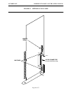
NOTE: When building adapters from these diagrams, keep in mind that the connections between the AXXESS RS-232-C
port and the DB9 or DB25 port include the modular adapter and a line cord. The connection must be made as indicated
in the diagram (correct pins connected) regardless of whether a reversing or non-reversing line cord is used.