


7
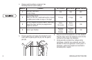
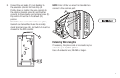
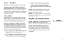
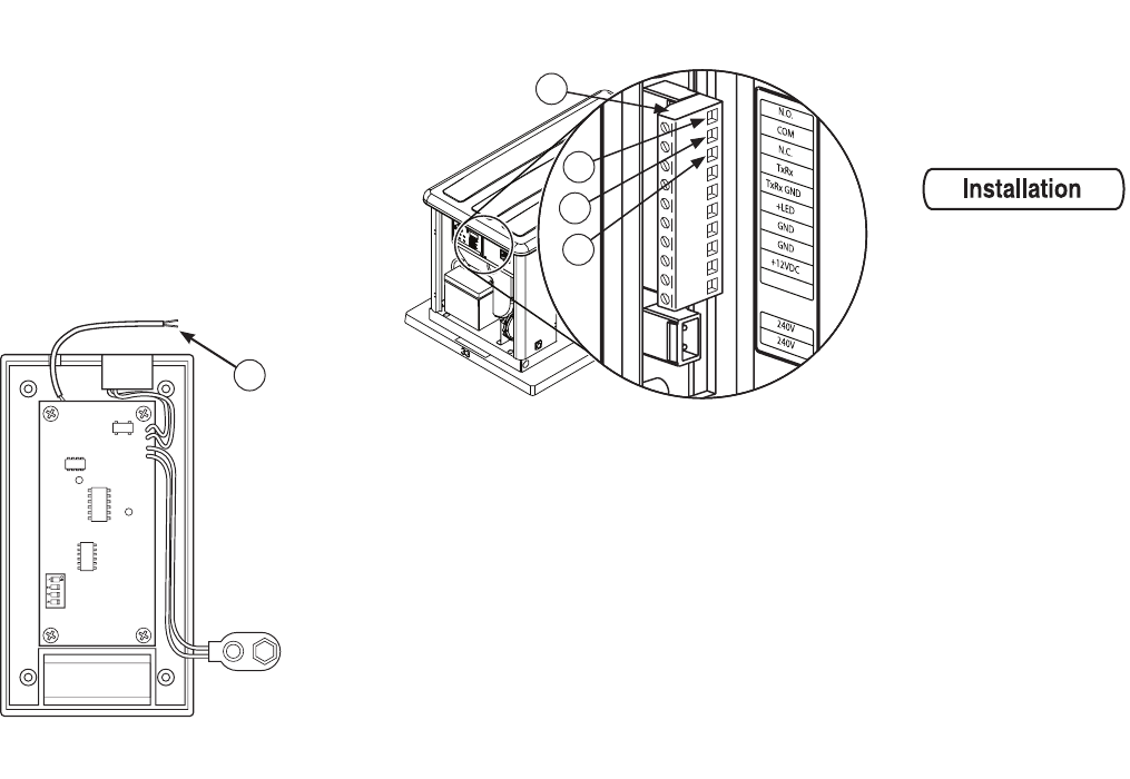
Connect the wire leads (C) from GenAlert to
the generator system’s terminal strip (D).
Polarity does not matter. One wire connects to
the common terminal screw (E) and the other
connects to the normally open terminal screw (F).
Dip Switch #4 must be in the default (ON)
position.
Should the above connection not be an option,
GenAlert can be modified to use the normally
closed terminal screw (G). Dip Switch #4 must be
changed to the (OFF) position.
C
8. NOTE: Either of the two wires from GenAlert can
connect to the common port.
F
E
G
D
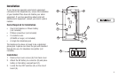
Extending Wire Lengths
If necessary, the phone cord or wire leads may be
extended up to 1,000 ft. (304 m).
Use a 2-conductor wire, 20 AWG or larger.