


INSTALLATION
6 7
The instructions below are for both table and wall installation.
1 Choose a spot near an electrical outlet and a telephone jack.
• This phone requires a modular telephone jack and a standard electrical
outlet (110v AC).
• The outlet should not be controlled by a wall switch; if the switch is
turned off, operation can be affected.
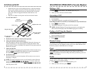
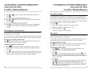
2 Install the handset battery.
• Remove the battery compartment cover on the handset by pressing on
the indentation and sliding the cover downward.
• Plug the battery pack cord into the handset, insert the battery pack and
rest the cords on top of the battery pack.
• Replace the cover by sliding it on its track up over the battery
compartment until it snaps firmly in place.
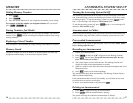
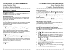
3 Set the handset ringer switch.
Set the switch on the side of the handset to ON so the handset will ring.
When this switch is set to OFF, the handset will not ring.
*
NOTE: If you set the ringer switch to OFF, the handset battery will last
longer. However, when the ringer switch is set to OFF, you will always
need to press on the handset to answer a call, even if the handset
has been in the base. When the ringer switch is set to OFF, the ANS SYS
light will not flash to indicate new messages.
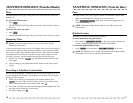
4 Connect the telephone line and power cords.
CAUTION: Use only the AC power adapter supplied with this
telephone. Power Supply HADW-1; Input: 120V AC, 60Hz, 16 W;
Output: 12V DC, 900mA
FOR TABLE INSTALLATION ONLY
• Plug one end of the telephone line cord into the jack on the base. Plug
the other end of the line cord into a modular phone jack. Make sure
the plug snaps firmly in place.
• Plug the power cord into the jack labeled POWER on the back of
the base. Plug the AC adapter on the power cord into an
electrical outlet.
*
NOTE: When the system is first connected to AC power, it will go
through an automatic initialization routine. After this routine is completed,
CL will flash in the message counter display, indicating that the clock
needs to be set. See “Setting the Clock” in the section on “ANSWERING
SYSTEM SET-UP.”
INSTALLATION
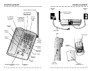
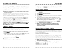
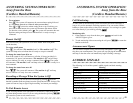
FOR WALL MOUNTING ONLY
Turn the base over and you will see a wedged, triangular-shaped plastic piece
that is attached to the bottom of the base. This is the mounting bracket. For
wall mounting, the mounting bracket must be attached to the base so that the
thickest end of the bracket is facing the floor (in wall mount position).
To wall mount the phone:
• Remove the mounting bracket by pushing in the two tabs at the large
end of the bracket and lifting the bracket from the base.
• Plug the power cord into the jack labeled POWER on the back of
the base. Guide the power cord from the jack through the straight
channel on the bottom of the base, so that any excess cord extends
straight out of the channel end farthest from the jack. Wrap any
excess cord around the two crescent-shaped tabs on the underside of
the mounting bracket but be sure to leave enough cord free to extend
to an electrical outlet.
• Plug one end of the telephone line cord into the jack on the base.
Guide the cord from the jack through the curved channel on the
bottom of the base. Wrap any excess cord around the two crescent-
shaped tabs on the underside of the mounting bracket but be sure to
leave enough cord free to extend to the wall jack. Take the end of the
cord and insert it through the rectangular-shaped hole in the center of
the bracket.
• Place the bracket back on the base so that the thickest end of the
bracket will be closest to the floor when in wall mount position.
• Plug the end of the telephone line cord into the modular phone jack
on the wall. Make sure the plug snaps firmly into place.