


2-222-22
2-222-22
2-22
Chapter 2: Hardware informationChapter 2: Hardware information
Chapter 2: Hardware informationChapter 2: Hardware information
Chapter 2: Hardware information
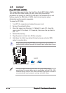
3.3.
3.3.
3.
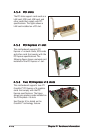
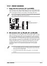
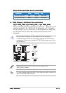
Serial ATA connectorsSerial ATA connectors
Serial ATA connectorsSerial ATA connectors
Serial ATA connectors
(7-pin SATA1 [red], SATA2 [red], SATA3 [black],(7-pin SATA1 [red], SATA2 [red], SATA3 [black],
(7-pin SATA1 [red], SATA2 [red], SATA3 [black],(7-pin SATA1 [red], SATA2 [red], SATA3 [black],
(7-pin SATA1 [red], SATA2 [red], SATA3 [black],
SATA4 [black])SATA4 [black])
SATA4 [black])SATA4 [black])
SATA4 [black])
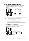
These connectors are for the Serial ATA signal cables for Serial ATA
hard disk drives.
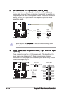
If you installed Serial ATA hard disk drives, you can can create a
RAID 0, RAID 1, RAID 0+1, RAID 5, and JBOD configuration. Refer to
Chapter 5 for information on creating a RAID configuration.
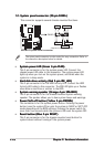
Enable the
Serial ATA Controller Serial ATA Controller
Serial ATA Controller Serial ATA Controller
Serial ATA Controller and
Onboard SATA Boot ROMOnboard SATA Boot ROM
Onboard SATA Boot ROMOnboard SATA Boot ROM
Onboard SATA Boot ROM
items in the BIOS if you want to use the Serial ATA RAID feature. See
section “4.3.5 Storage Configuration” for details.
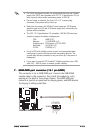
• Plug your Serial ATA boot disk on the master port (SATA1/2 to
support S3 function).
• Install the Windows
®
2000 Service Pack 4 or the Windows
®
XP
Service Pack1 or later when using Serial ATA.
A8R-MVP
®
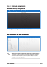
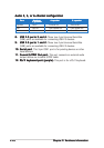
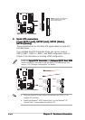
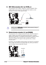
A8R-MVP IDE connectors
NOTE: Orient the red marking
s
(usually zigzag) on the IDE
ribbon cable to PIN 1.
PRI_IDE
PIN 1
SEC_IDE
A8R-MVP
®
A8R-MVP SATA connectors
SATA1
GND
RSATA_TXP1
RSATA_TXN1
GND
RSATA_RXP1
RSATA_RXN1
GND
SATA4
GND
RSATA_TXP4
RSATA_TXN4
GND
RSATA_RXP4
RSATA_RXN4
GND
SATA3
GND
RSATA_TXP3
RSATA_TXN3
GND
RSATA_RXP3
RSATA_RXN3
GND
SATA2
GND
RSATA_TXP2
RSATA_TXN2
GND
RSATA_RXP2
RSATA_RXN2
GND