- 7 -
1-1
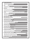
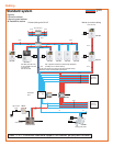
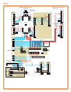
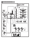
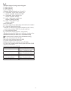
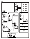
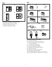
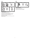
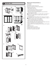
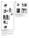
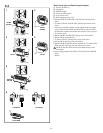
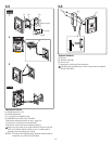
Standard System Configuration Diagram
(1) Audio signal line
(2) Video signal line
(3) Power supply line
a. Entrance station (For details, see 2-1 and 2-2)
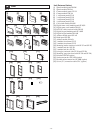
[1] Video/audio + digital name scrolling type
GH-VA + GH-DA + GH-NS, GH-10K
[2] Video/audio + direct selection type
GH-VA + GH-DA + GH-SW
[3] Audio + digital name scrolling type
GH-DA + GH-NS, GH-10K
[4] Audio + direct selection type
GH-DA + GH-SW
b. Bus control units
[5] Power supply adapter PS-2410LC, PS-2410LD, PS-2410DIN
[6] Video bus control unit GH-VBC
∗ GH-VBC can be used as an extension adapter as well. To do so,
set the setting switch to "EXP." (2 units per trunk line)
[7] Bus control unit GH-BC
[8] Distribution terminal (junction): sold separately
c. Residential station (For details, see 2-4):
Station-to-station wiring
d. Residential station (For details, see 2-4): Homerun wiring
Do not mix station-to-station wiring and homerun wiring.
[9] 4-way video junction unit GH-4Z
[10] Color video residential station GH-1KD
[11] Audio residential station GH-1AD
[12] Black &White video residential station GH-1MD
[13]
Color video residential station +handset (option) GH-1KD + GH-HS
e. Security Guard Station
[14] Security guard station GH-MK
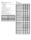
Capacity
Entrance Station Maximum 5 stations
(up to 3 stations per trunk)
Residential Station Maximum 48 stations
(up to 25 stations per trunk)
Security Guard Station Maximum 2 stations
Residential stations
in the same residence
Maximum 4 stations
(up to 2 monitor stations)
4-way video junction unit Maximum 6 units per trunk


