


- 19 -
4-1
4-2
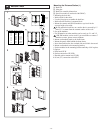
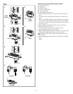
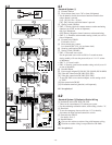
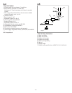
Standard System (1)
[1] Entrance Station
[2] Door release timer (set to "M" at time of shipment)
• Set the duration for the door release function when the door
release button is pressed.
[0.5] - [20]: 0.5 secs - 20 secs
[20] - [M]: Activates while the button is pressed.
[3] Setting switch (GH-DA)
• SW2: 1: Setting switch for camera entrance station monitoring
function (set to OFF at time of shipment)
ON (Up): Monitored.
OFF (Down): Skipped at time of entrance station monitoring.
• SW2: 2 - 4: Entrance station number setting switch (set to #1 at
time of shipment)
[4] External relay GH-RY
For details, see 4-5.
[5] Door release relay contact
Less than AC/DC 24 V, 4 A (resistance load)
[6] Security guard station GH-MK
[7] Setting switch (GH-MK)
• SW1: 1: Password reset switch
Set the password reset switch to ON for 2 seconds or more
during standby will reset the password (set to "∗1111" at time
of shipment).
• SW1: 2, 3: Unused switch
• SW1: 4: Security guard station number setting switch (set to #1
at time of shipment)
[8] Doorbell button
[9] Power supply adapter PS-2410LC, PS-2410LD, PS-2410DIN
[10] Video bus control unit GH-VBC (SW: STD)
[11] Video bus control unit GH-VBC (SW: EXP)
• To use GH-VBC as an extension adapter, set the setting switch
to "EXP."
[12] Bus control unit GH-BC
[13] Distribution terminal (junction): sold separately
NP: Non-polarized
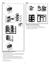
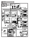
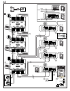
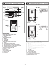
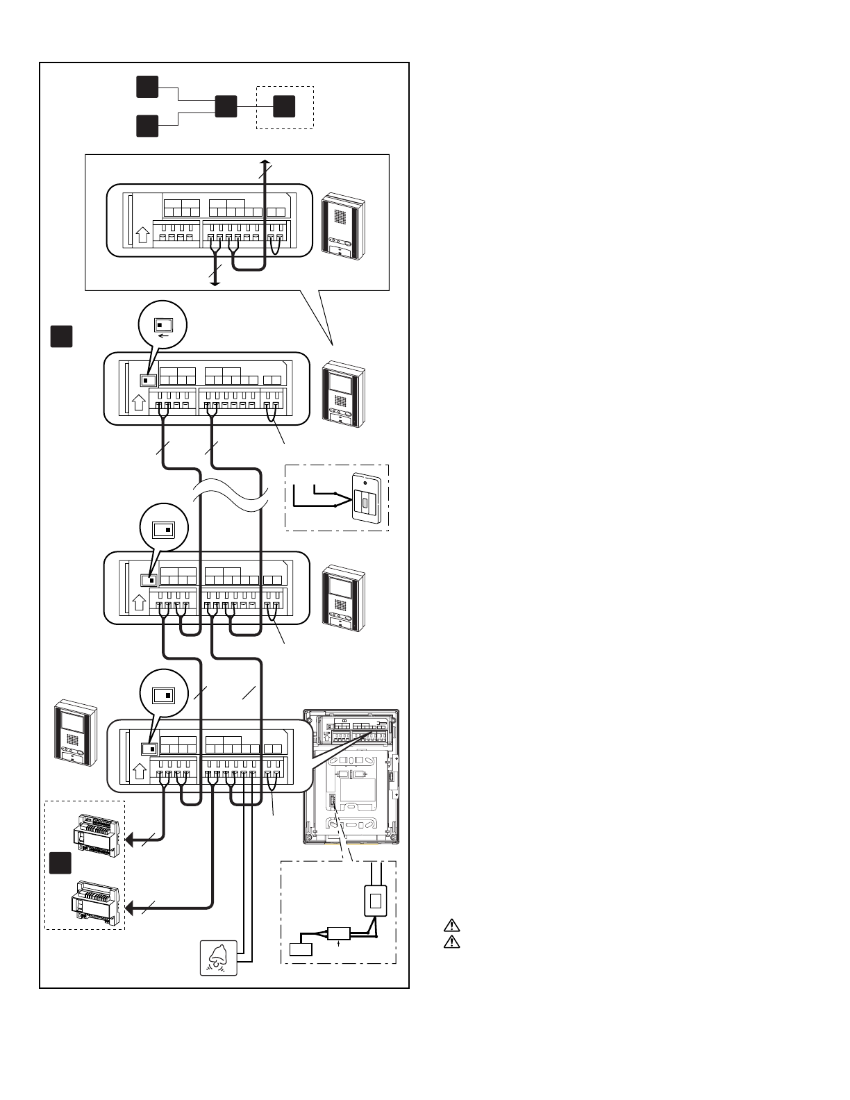
Standard System (2) Station-to-Station Wiring
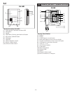
[1] Residential station GH-1KD, GH-1AD
• There can be a maximum of 25 stations per system.
•
For the terminating residential station, set the setting switch to "A".
[2] Short lead
• To use the emergency alarm switch (see 11-7 for details),
disconnect the short lead and connect the switch.
[3] External relay GH-RY
For details, see 4-5.
[4] Doorbell button
1. Do not mix station-to-station wiring with homerun wiring.
2. Station-to-station wiring is not possible for GH-1MD.
NP: Non-polarized
4-2
SW1 A B
IN OUT
R1 R2 R1 R2 C
0.65 10 9
CE K KE
Do not remove the wires (For end users)
SW1
A
B
[1]
[4]
GH-VBC
GH-BC
b
GH-1KD
GH-1KD
GH-1KD
SW1
A
B
SW1
B
A
c
1P
NP
1P
NP
1P
NP
1P
NP
1P
NP
1P
NP
AC
B
GH-RY
[3]
[2]
[2]
[2]
GH-1AD
IN OUT
R1R2R1R2 C CE K KE
IN OUTIN OUT
R1R2R1R2B1B2B1B2 C CE K KE
IN OUTIN OUT
R1R2R1R2B1
B2
B1B2 C CE K KE
IN OUTIN OUT
R1R2R1R2B1
B2
B1B2 C CE K KE
1P
NP
1P
NP
R1, R2
b
a
e
c
KEK